Complete equipment for continuous laser welding

A technology of laser welding and complete sets of equipment, applied in laser welding equipment, welding equipment, metal processing equipment and other directions, can solve the problems of automatic welding of unfavorable parts, worker's hand injury, vulnerability to injury, etc., to achieve simple and convenient operation and reduce injury , to ensure the effect of precision

Active Publication Date: 2020-12-08
RICH HIGH TECH CO LTD
View PDF6 Cites 0 Cited by
  • Summary
  • Abstract
  • Description
  • Claims
  • Application Information

AI Technical Summary

Problems solved by technology

In the past, during the welding process, workers were required to hold two parts and make the sides of the two parts touch each other, but this is easy to cause damage to the hands of workers
Now, although there is no need for workers to hold the parts to fix the parts, which solves the problem that the workers' hands are vulnerable to injury, it is necessary to fix the two parts to the clamping mechanism before each welding, and then remove the two parts from the clamping mechanism after welding. The opening and closing of the clamping mechanism are all manual operations, so for the entire welding process, the efficiency is relatively low, which is not conducive to the streamlined and automatic welding of parts

Method used


Image

  • Complete equipment for continuous laser welding
  • Complete equipment for continuous laser welding
  • Complete equipment for continuous laser welding

Examples


Embodiment 1

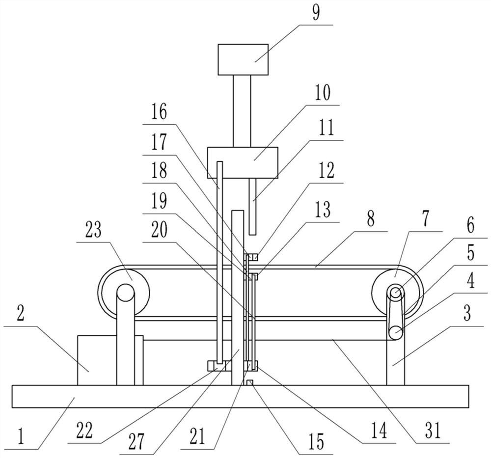
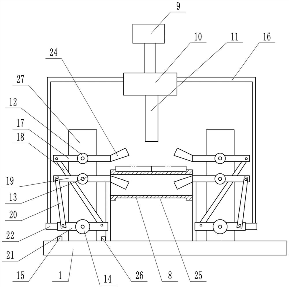
[0024] Basic as attached figure 1 Shown: a complete set of equipment for continuous laser welding, including a frame, a base 1 is welded on the frame, two support frames 3 are welded on the base 1, and a driven roller 23 is connected to the support frame 3 on the left through shaft rotation. A driving roller 7 is connected to the support frame 3 on the right side through shaft rotation, and a conveyor belt 8 is connected between the driving roller 7 and the driven roller 23 . On the support frame 3 on the right side, a motor (not shown) is fixed by screws, and a belt pulley 6 is coaxially welded on the drive roller 7 , and a belt 5 is connected between the output shaft 4 of the motor and the pulley 6 . combine figure 2 As shown, the thickness of the middle part of the conveyor belt 8 is less than the thickness of the two sides of the conveyor belt 8, so the middle part of the conveyor belt 8 forms a groove 25, thereby the parts can be limited to prevent the parts from figu...

Embodiment 2

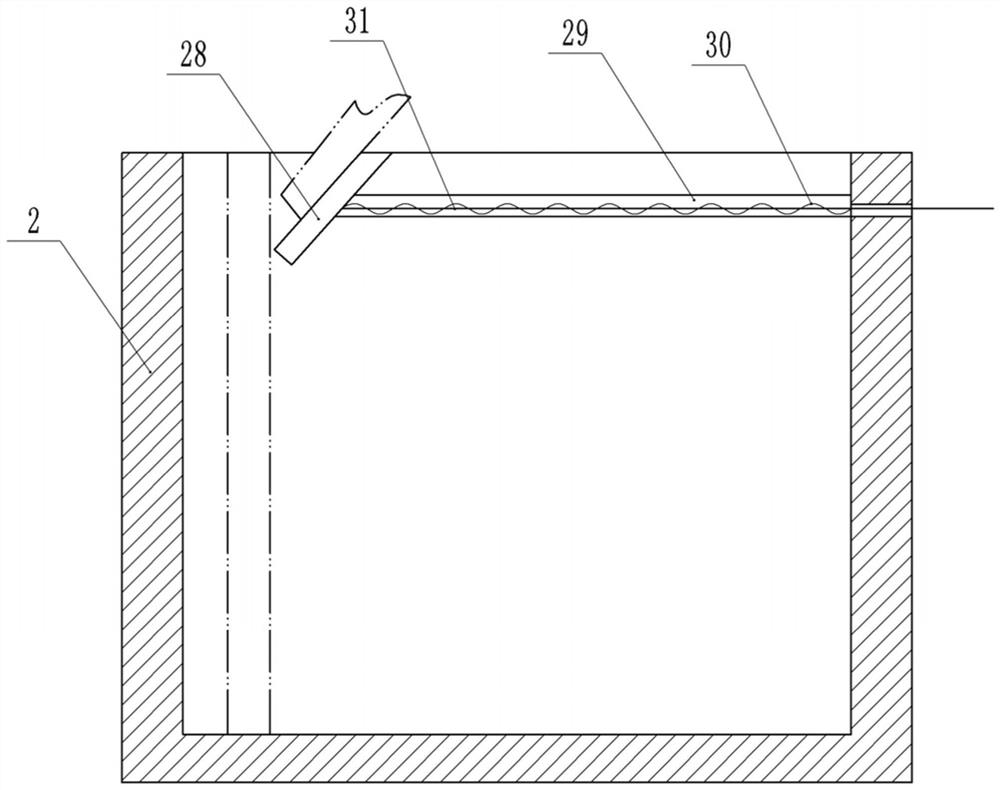
[0034] combine figure 1 As shown, a collection box 2 is provided below the driven roller 23, and the collection box 2 is slidably connected to the base 1 from left to right. bumps in slots. combine image 3 As shown, the top of the collection box 2 is slidably connected with an inclined guide plate 28. Specifically, the inner wall of the collection box 2 is provided with a laterally arranged chute 29, and the side of the guide plate 28 is integrally formed with a sliding connection on the chute. 29 inner bumps. The right side wall of collection box 2 is provided with rope hole, and one end of stay rope 31 is bolted on the support frame 3 where driving roller 7 is located, and stay rope 31 other ends pass rope hole and are bolted on the guide plate 28, and guide plate An elastic member is connected between 28 and the right inner wall of the collection box 2, and the elastic member is a compression spring 30 in this embodiment.

[0035] combine Figure 4 As shown, the base ...

Embodiment 3

[0039] In this embodiment, the laser 10 can slide on the cylinder rod, so that the laser 10 can be moved laterally to adapt to welding parts with different widths.


PUM


Abstract

The invention relates to the field of automatic welding, in particular to complete equipment for continuous laser welding. The complete equipment for continuous laser welding comprises a clamping mechanism, a laser welding mechanism is slidably connected above the clamping mechanism, the clamping mechanism comprises a vertical frame, the vertical frame is rotatably connected with a first rotating column, a second rotating column and a third rotating column, the first rotating column, the second rotating column and the third rotating column are fixedly connected with a first cross bar, a second cross bar and a third cross bar respectively, clamping heads are arranged at the end parts of the first cross bar and the second cross bar, the other ends of the first cross bar and the second cross bar are rotatably connected with a first connecting rod and a second connecting rod respectively, one end of the first connecting rod and one end of the second connecting rod are rotatably connected with the two ends of the third cross bar correspondingly, the third rotating column is fixedly connected with a driving handle, and a driving rod is connected between the laser welding mechanism and the driving handle; and the equipment further comprises a conveying mechanism, and the lower parts of the two ends of the third cross bar are provided with a first button and a second button correspondingly. According to the scheme, parts are automatically clamped and loosened, and the whole welding efficiency is improved.

Description

technical field [0001] The invention relates to the field of automatic welding, in particular to a complete set of equipment for continuous laser welding. Background technique [0002] Laser welding is an efficient and precise welding method that uses a high-energy-density laser beam as a heat source. Laser welding is one of the important aspects of the application of laser material processing technology. In the 1970s, it was mainly used for welding thin-walled materials and low-speed welding. The welding process is heat conduction, that is, the laser radiation heats the surface of the workpiece, and the surface heat diffuses to the inside through heat conduction. By controlling the width, energy, peak power and repetition frequency of the laser pulse and other parameters to melt the workpiece and form a specific molten pool. Due to its unique advantages, it has been successfully applied to the precision welding of micro and small parts. [0003] At present, in the manufa...

Claims


Application Information

Patent Timeline
Patent Type & Authority Patents(China)
IPC IPC(8): B23K26/21B23K26/70
CPCB23K26/21B23K26/702
Inventor 张还孙兵涛
Owner RICH HIGH TECH CO LTD
Why Eureka
Try Eureka