Negative bending moment area UHPC treatment steel-concrete composite structure and preparation method thereof

A technology of negative bending moment area and combined structure, which is applied to bridge parts, bridge materials, bridges, etc., to achieve the effects of being easy to promote and use, enhancing integrity, and solving cracking problems

Pending Publication Date: 2019-09-17
CCCC SECOND HIGHWAY CONSULTANTS CO LTD
View PDF0 Cites 10 Cited by
  • Summary
  • Abstract
  • Description
  • Claims
  • Application Information

AI Technical Summary

Problems solved by technology

UHPC can increase the cracking load of composite beams in the negative bending moment area. Under the action of negative bending moments, the cracking strength of steel-UHPC continuous composite beams is much higher than that of ordinary steel-concrete composite beams, and the crack spacing is smaller, which significantly inhibits The development of concrete cracks can effectively solve the problem of cracking in the negative moment zone of steel-concrete bridge deck continuous composite beams

Method used


Image

  • Negative bending moment area UHPC treatment steel-concrete composite structure and preparation method thereof
  • Negative bending moment area UHPC treatment steel-concrete composite structure and preparation method thereof
  • Negative bending moment area UHPC treatment steel-concrete composite structure and preparation method thereof

Examples


Embodiment 1

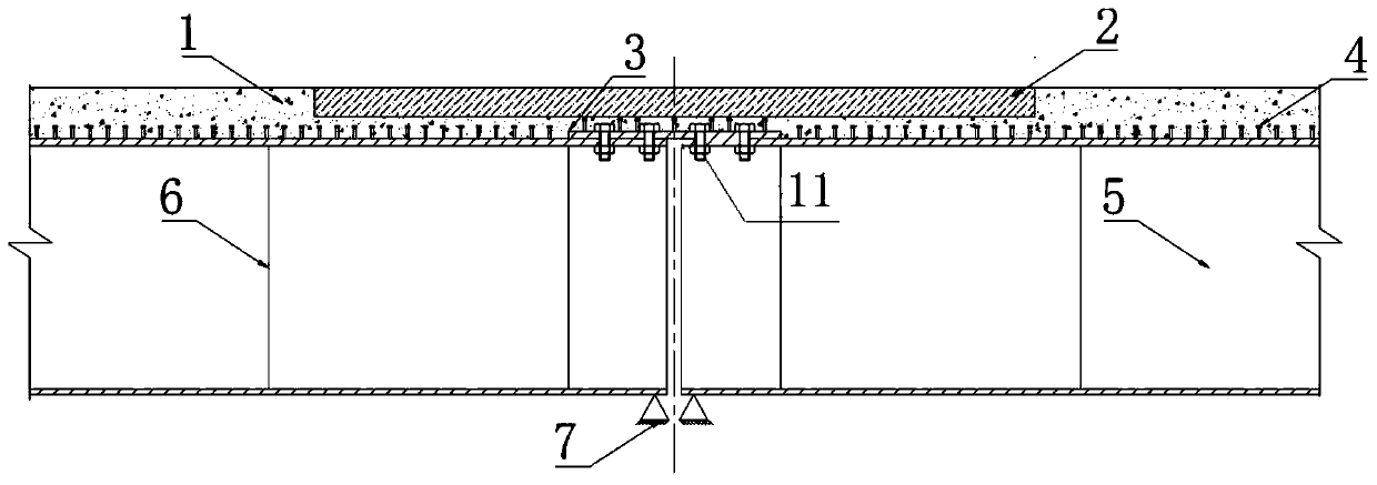
[0040] Such as Figure 1~4 , the laying process is as follows in the present embodiment:

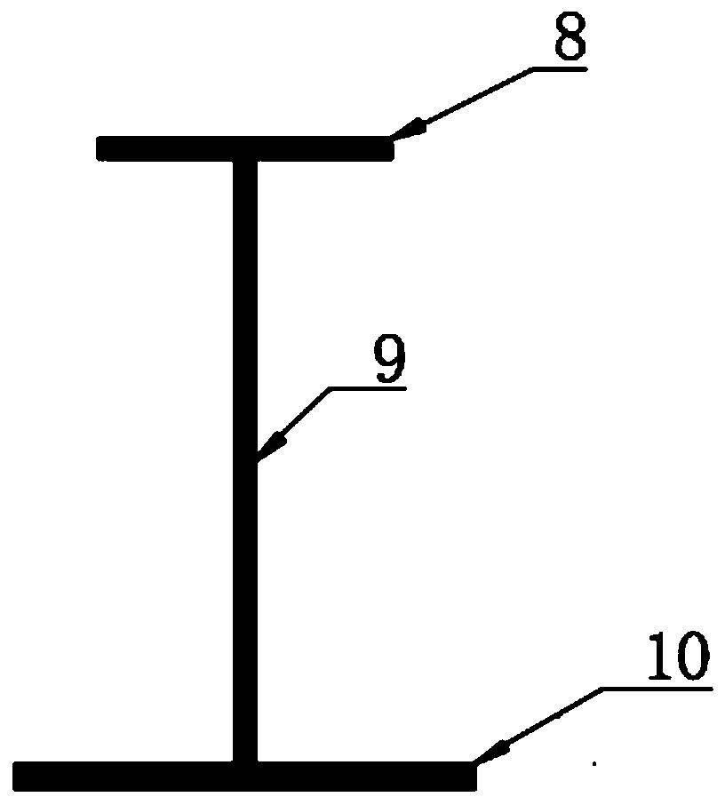
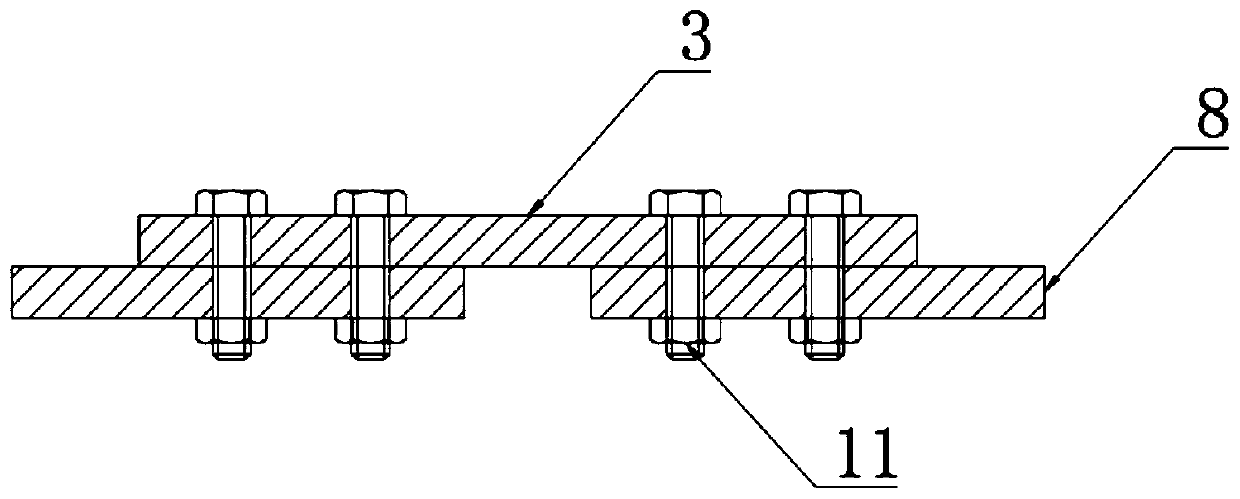
[0041] Steel girders 5 are erected at equidistant intervals within a section of span L formed by every two piers 7, the steel girders 5 are I-shaped steel girders, and the steel girder webs 9 are equidistantly arranged with steel girder stiffeners 6 along the length direction , at the negative bending moment zone on the pier 7, use steel plate 3 to bolt or weld the upper flange 8 of the steel girder in the adjacent span L, and the pier 7 is arranged according to the span L being 30-60m;

[0042] Then weld the shear nail 4 on the upper surface of the steel plate 3 and the upper flange 8 of the steel beam;

[0043] A continuous prefabricated ordinary concrete bridge deck 1 is laid on the upper surface of the steel plate 3 and the upper flange 8 of the steel beam. The negative bending moment zone of the ordinary concrete bridge deck 1 on the pier 7 has a concave cavity, and the UHPC bridg...

Embodiment 2

[0049] Such as Figure 1~5 , the laying process is as follows in the present embodiment:

[0050] Steel girders 5 are erected at equidistant intervals within a span L formed by every two piers 7, the steel girders 5 are I-shaped steel girders, and steel plates 3 are bolted or welded at the negative moment zone on the pier 7 The upper flange 8 of the steel girder adjacent to the span L, and the piers 7 are arranged according to the span L being 30-60m;

[0051] Then weld the shear nail 4 on the upper surface of the steel plate 3 and the upper flange 8 of the steel beam;

[0052] The steel girder stiffeners 6 are welded and fixed equidistantly along the length direction of the steel girder web, and a continuous ordinary concrete bridge deck 1 is laid on the upper surface of the steel plate 3 and the upper flange 8 of the steel girder by template method, and the ordinary concrete bridge deck 1 The negative bending moment zone on the pier 7 has an inner cavity, and the UHPC brid...


PUM


Abstract

The invention discloses a negative bending moment area UHPC treatment steel-concrete composite structure and a preparation method thereof. An UHPC bridge deck slab is adopted within a segment length of a steel-concrete composite structure negative bending moment area; and a top flange of an adjacent steel girder is welded (bolted) to a pier top. For a steel-concrete simply supported bridge deck continuous composite structural beam, the negative bending moment area UHPC treatment steel-concrete composite structure has the advantages that the cracking load of the negative bending moment area composite beam can be obviously increased; and due to smaller fracture interval, the development of a concrete crack can be obviously suppressed; and the excellent anti-cracking performance can effectively solve the cracking problem of the negative bending moment area.

Description

technical field [0001] The invention belongs to the technical field of steel-concrete composite structures, and in particular relates to a UHPC-treated steel-concrete composite structure in a negative moment zone and a preparation method thereof. Background technique [0002] With the continuous development of highway and urban construction in our country, steel-concrete composite girder bridges have been widely used due to their advantages such as large spanning capacity, small building height, good seismic performance and fast construction. Steel-concrete composite beams have become a common structural form in municipal engineering, highway engineering, and construction engineering. With the development of bridges towards lighter weight and longer spans, steel-concrete composite beams have also developed from simply supported structures to multi-span continuous structures. However, as Zheng Hehui et al. introduced in the paper "Steel-Concrete Composite Continuous Beam Bri...

Claims


Application Information

Patent Timeline
Patent Type & Authority Applications(China)
IPC IPC(8): E01D19/12E01D2/02E01D101/24E01D101/30
CPCE01D2/02E01D19/125E01D2101/24E01D2101/30
Inventor 刘新华李秋孙武云彭元诚范新荣吴晓勤
Owner CCCC SECOND HIGHWAY CONSULTANTS CO LTD
Why Eureka
Try Eureka