Self-stress bridge continuous construction structure based on simply supported steel beams and construction method thereof

A technology of self-stress and steel girders, applied in bridges, bridge materials, bridge construction, etc., can solve the problems of lack of continuous structural structures and construction methods, large differences in self-stress values, and no self-stress connecting plates, etc., to achieve The expansion response is compact, the elastic modulus is close, and the effect of improving the coordination of deformation

Pending Publication Date: 2022-07-22
SHANDONG UNIV
View PDF7 Cites 0 Cited by
  • Summary
  • Abstract
  • Description
  • Claims
  • Application Information

AI Technical Summary

Problems solved by technology

[0005] However, the self-stress value produced by using different expansion agent materials to make bridge deck connection plates varies greatly, and there is no formula suitable for the stress value required by the connection plate. At the same time, there is no relevant application of self-stress connection plates in bridge continuous construction. Literature, lack of corresponding continuous construction structures and construction methods

Method used


Image

  • Self-stress bridge continuous construction structure based on simply supported steel beams and construction method thereof
  • Self-stress bridge continuous construction structure based on simply supported steel beams and construction method thereof
  • Self-stress bridge continuous construction structure based on simply supported steel beams and construction method thereof

Examples


Embodiment 1

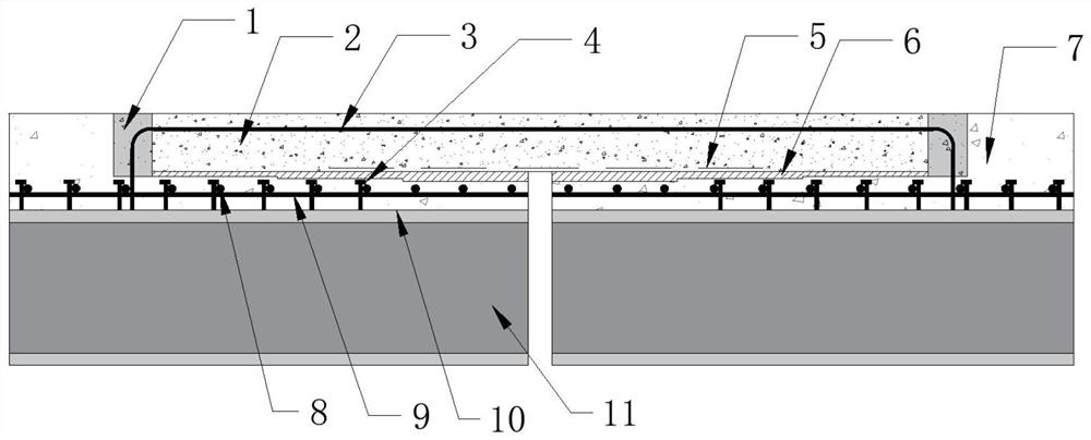
[0079] A self-stressed bridge continuous structural structure based on simply supported steel beams, such as Figure 1-5 As shown, it includes a self-stressing connection plate 2, an elastic deformation layer 1, a bridge deck pavement layer 7, a buffer energy-absorbing layer 6 and a connection structure;

[0080] The self-stressed connecting plate 2 is located between the two H-shaped steel beams 11, and the self-stressed connecting plate 2 is made of self-stressed concrete material through formwork casting, and the bottom of the self-stressed connecting plate 2 is provided with a debonding tape 5;

[0081] The elastic deformation layer 1 is arranged at both ends of the self-stressed connecting plate and is an elastic concrete material;

[0082] The bridge deck pavement layer 7 is located above the H-shaped steel beam 11, and an interface adhesive 10 is applied between the H-shaped steel beam 11 and the bridge deck pavement layer 7. The interface adhesive 10 is made of vinyl a...

Embodiment 2

[0087] A self-stressed bridge continuous structural structure based on simply supported steel beams, as described in Example 1, the difference is that the length of the self-stressed connecting plate 2 is 3.8m in span length and 3.8m in thickness of two adjacent bridge spans. The width of 0.12m is set according to the width of each linear meter (1m); the length of the debonding tape is 2 meters, and the material of the debonding tape 5 is 350# roofing paper, which has strong tensile ability and can better adapt to H-shaped steel beams It can be stretched and deformed with the self-stressed connecting plate, and at the same time, the waterproof performance is excellent, and it is preferably set in the middle part of the length of the self-stressed connecting plate;

[0088] The elastic concrete material of the elastic deformation layer 1 includes polyurethane binder, cement, standard sand and fibers, which are mixed and stirred. The polyurethane binder includes two components, p...

Embodiment 3

[0093] A self-stressed bridge continuous structural structure based on simply supported steel beams, as described in Example 2, the difference is that the bridge deck pavement layer 7 sequentially includes modified asphalt concrete surface layer, epoxy resin waterproofing layer from top to bottom Adhesive layer and C40 ordinary concrete layer, the interface adhesive 10 is applied between the C40 ordinary concrete layer and the H-shaped steel beam, and the lower part is a steel mesh formed by binding longitudinal steel bars and structural steel bars, and the bridge deck pavement layer The structure of each material functional layer is not much different from the traditional bridge deck pavement layer. figure 2 In the unified use of concrete symbols;

[0094] The longitudinal part of the inverted U-shaped steel bar 3 is 30mm away from the top of the self-stressed connecting plate 2, and the inverted U-shaped steel bar is preferably 3.9 meters long and 0.19 meters high, HRB335, ...


PUM


Abstract

The invention relates to a self-stress bridge continuous construction structure based on simply supported steel beams and a construction method thereof, and belongs to the field of bridge engineering structures and civil engineering materials, the self-stress bridge continuous construction structure comprises a self-stress connecting plate, an elastic deformation layer, a bridge deck pavement layer, a buffer energy absorption layer and a connecting structure; the self-stress connecting plate is made of a self-stress concrete material; the elastic deformation layers are arranged at the two ends of the self-stress connecting plate and are made of elastic concrete materials. An interface binder is smeared between the H-shaped steel beam and the bridge deck pavement layer, and the buffer energy absorption layer is a polytetrafluoroethylene rubber gasket; the connecting structure comprises inverted-U-shaped steel bars, shear nails, longitudinal steel bars and constructional steel bars, and the longitudinal parts of the inverted-U-shaped steel bars transversely penetrate through the self-stress connecting plates, are bent downwards in an arc shape in the elastic deformation layer and penetrate through the bridge deck pavement layer to be welded to the H-shaped steel beams. The connecting plate is made of a self-stress concrete material, and the self-stress bridge continuous construction structure is reasonable, so that the self-stress concrete connecting plate is better applied to the bridge connection construction structure.

Description

technical field [0001] The invention relates to a self-stressed bridge continuous structure structure based on simply supported steel beams and a construction method thereof, belonging to the fields of bridge engineering structures and civil engineering materials. Background technique [0002] In order to solve a series of problems caused by expansion joints, simply supported girder bridges mostly adopt the structural form of continuous simply supported girder bridges. The bridge deck is continuous, making it a continuous bridge with a seamless middle and a seamless mid-span. However, the existing ordinary concrete bridge connecting plates are prone to cracks in the tensile area under the actual load. With the further development of cracks, the durability of concrete down, eventually causing the bridge deck connecting plate to fail. [0003] In order to solve the above problems, the post-tensioning method is usually used to apply pre-compression stress to the continuous mem...

Claims


Application Information

Patent Timeline
Patent Type & Authority Applications(China)
IPC IPC(8): E01D21/00E01D19/12E01D19/00E01D101/28
CPCE01D21/00E01D19/125E01D19/00E01D2101/28
Inventor 葛智王聿梁管延华苏建明薛志超孙仁娟张洪智凌一峰王丽君高天明
Owner SHANDONG UNIV
Why Eureka
Try Eureka