A method of using building formwork during construction

A technology for building formwork and formwork, which is applied to formwork/formwork/work frame, on-site preparation of building components, construction, etc. The effect of building efficiency

Active Publication Date: 2020-12-15
CITIC GUOAN CONSTR GRP CO LTD
View PDF4 Cites 0 Cited by
  • Summary
  • Abstract
  • Description
  • Claims
  • Application Information

AI Technical Summary

Problems solved by technology

Due to the complex process, it is easy to cause quality problems and delay the construction period
Especially for high-supported concrete floors, the traditional method is to build a full hall frame under the post-casting belt, and then install the supporting formwork. The formwork is installed by hoisting, that is, brackets are installed on the concrete on both sides of the post-casting belt, and then the formwork is lifted to the bottom of the post-casting belt by a lifting device, the formwork is connected to the support, and the upward binding force is generated on the formwork by the support to realize The purpose of fixing the formwork below the post-pouring belt, but the above-mentioned method cannot quickly connect the formwork to the support above the post-casting belt due to the height of the post-casting belt and the lower ground, resulting in low construction efficiency; Before the belt is poured, the construction workers are easy to fall from the post-cast belt to be poured, or the construction waste during construction falls onto the post-cast belt to be poured, and after the concrete is poured on the post-cast belt, the concrete is condensed During the process, construction impurities are easy to fall onto the post-casting belt to be condensed, affecting the quality of the post-casting belt

Method used


Image

  • A method of using building formwork during construction
  • A method of using building formwork during construction
  • A method of using building formwork during construction

Examples


Embodiment 1

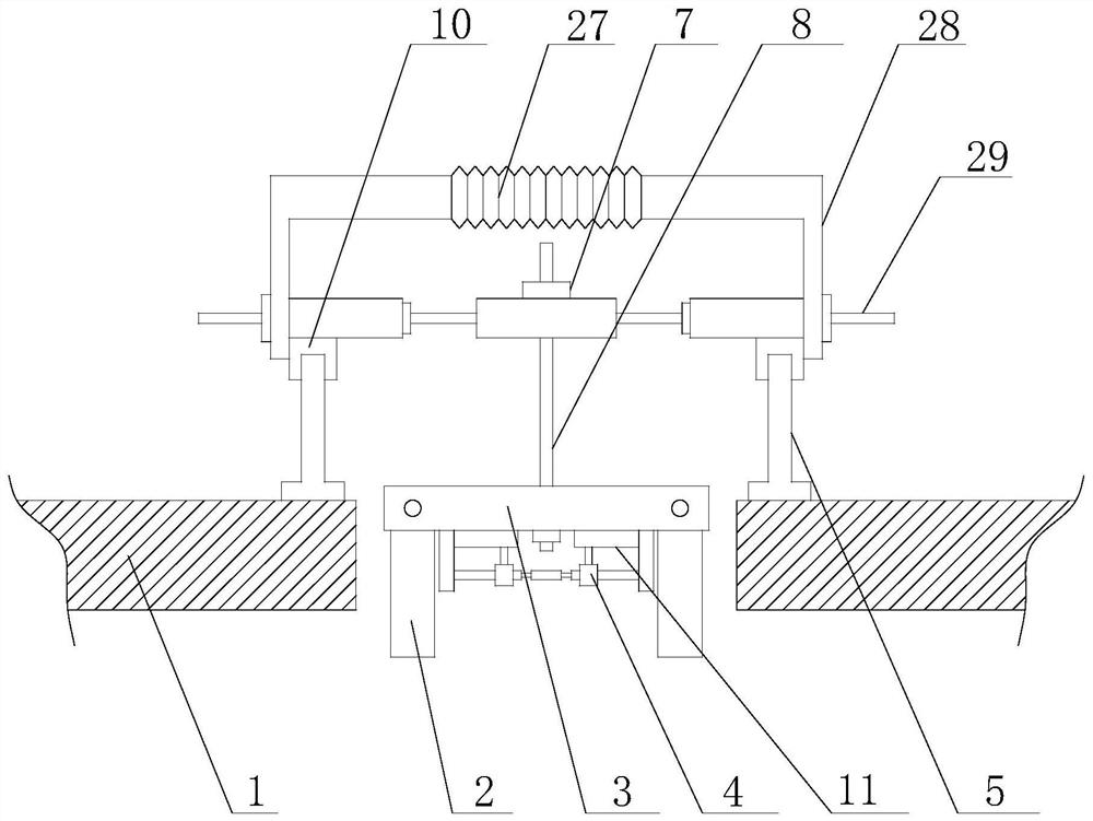
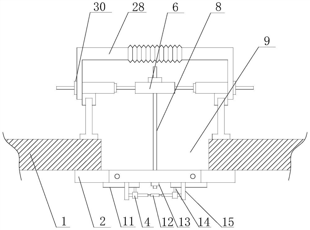
[0055] A method for using a building formwork in the present invention, 1. After finishing the pouring of the concrete 1 floor slabs on both sides of the post-cast belt 9, the support frame 5 is installed on the concrete 1 on both sides of the post-cast belt 9 to be corrected;

[0056] 2) Adjust the length of the horizontal plate 6 according to the width of the post-casting belt 9, and connect the moving block 10 with the support frame 5, so that the horizontal plate 6 is installed above the post-casting belt 9 to be poured;

[0057] 3) Install the connecting plate 28 and connect it with the adjusting rod 29, and use the baffle to protect the post-casting belt 9;

[0058] 4) When it is necessary to pour concrete on the post-pouring belt 9, connect the threaded rod 8 connected to the template 3 with the horizontal plate 6 through the nut 7;

[0059] 5) Rotate the nut 7, and the threaded rod 8 drives the formwork 3 to move downward in the vertical direction, so that the formwork...

Embodiment 2

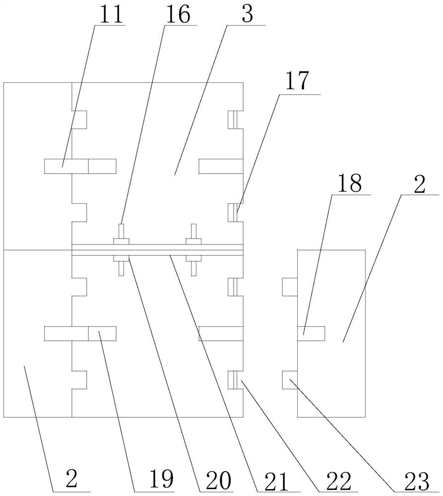
[0069] On the basis of Embodiment 1, the fixed assembly includes a rotating rod 12, two connecting blocks 15, and two moving plates 11. The connecting blocks 15 are respectively located on both sides of the axis of the template 3, and the two ends of the rotating rod 12 are respectively It is connected with two connecting blocks 15, and the rotating rod 12 can rotate in the connecting block 15. The moving plate 11 is located at the bottom of the template 3, and the moving plate 11 runs through the connecting block 15 horizontally. Rotating the rotating rod 12, the moving plate 11 can move along the horizontal direction in the connection block. The two ends of described rotating bar 12 are all provided with movable block 4, and movable block 4 is connected with rotating bar 12 by screw thread, and described movable block 4 is all provided with connecting rod 14, and connecting rod 14 is connected with moving plate 11, movable When the block 4 moves on the rotating rod 12, the c...

Embodiment 3

[0071] On the basis of Embodiment 2, two connecting grooves 22 are provided at both ends of the template 3, and two connecting blocks matching the connecting grooves 22 are provided on the side wall of the movable support plate 2 facing the direction of the template 3 23, the connecting block 23 is located in the connecting groove 22, the connecting groove 22 is also provided with a movable shaft 17, and the movable shaft 17 is inserted in the connecting block 23, and the connecting block 23 can rotate on the movable shaft 17.


PUM


Abstract

The invention discloses a using method of a building template in construction. The building template comprises a support frame arranged on concrete, a plurality of cross plates are arranged on the support frame, the cross plates are distributed on the support frame along a post-cast strip, each cross plate is provided with a threaded rod and a nut, the threaded rod can move on the cross plates in the vertical direction, the nut is connected with the threaded rod, and the nut is located at the top of the cross plate; a template is arranged at the bottom of the threaded rod, each threaded rod is further provided with a nut cap, the nut cap is located at the bottom of the template, thus the template is detachably connected with the threaded rod, the length of the template is smaller than the width of the post-cast strip, moving support plates are correspondingly arranged on the two sides of the direction, facing the concrete, of the template, the moving support plates are hinged to the template, and the moving support plates can rotate on the template; and a fixing assembly is further arranged at the bottom of the template, and the upper surfaces of the moving support plates and the upper surface of the template can be on the same horizontal line through the fixing assembly.

Description

technical field [0001] The invention relates to the technical field of building construction, in particular to a method for using a building formwork during construction. Background technique [0002] The post-cast belt is to prevent the harmful cracks that may occur in the cast-in-place reinforced concrete structure due to temperature, uneven shrinkage, and settlement deformation during construction. According to the requirements of design or construction specifications, temporary The construction joint temporarily divides the structure into several parts, and after a certain period of time, the concrete of the construction joint is poured and tamped after the internal shrinkage and settlement deformation of the components to connect the structure into a whole. In the construction of building structures, the construction of the post-pouring belt of the concrete slab is a very important link. Due to the complex process, it is easy to cause quality problems and delay the con...

Claims


Application Information

Patent Timeline
Patent Type & Authority Patents(China)
IPC IPC(8): E04G13/00
CPCE04G13/00
Inventor 张学华李勇刘宇李鹏马均海蔡伦
Owner CITIC GUOAN CONSTR GRP CO LTD
Why Eureka
Try Eureka