A device for naturally drying cutting slag and pressing bricks

A technology of natural drying and cutting slag, applied in drying chamber/container, drying solid materials, drying gas arrangement, etc., can solve the problems of incomplete drying, affecting the quality of finished bricks in drying efficiency, and ensure drying uniformity and stability. Contact area, the effect of improving drying efficiency

Active Publication Date: 2020-09-08
永平县泰达废渣开发利用有限公司
View PDF4 Cites 0 Cited by
  • Summary
  • Abstract
  • Description
  • Claims
  • Application Information

AI Technical Summary

Problems solved by technology

[0003] The technical problem to be solved by the present invention is: during the brick drying process, air cannot circulate between the contact surfaces of the stacked bricks and the drying is not thorough, which affects the drying efficiency and the quality of the finished bricks. Equipment for pressing bricks to dry naturally

Method used


Image

  • A device for naturally drying cutting slag and pressing bricks
  • A device for naturally drying cutting slag and pressing bricks
  • A device for naturally drying cutting slag and pressing bricks

Examples


Embodiment 1

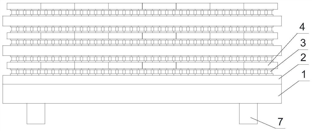
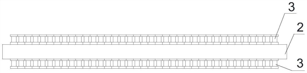
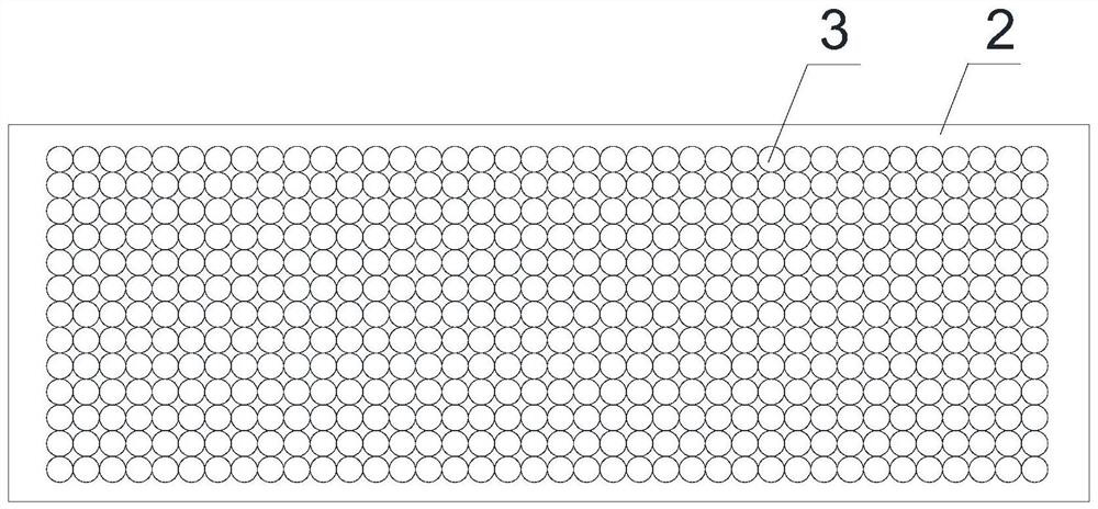
[0035] This embodiment provides a device for naturally drying cutting slag and pressing bricks, which includes a base 1 and a plurality of support plates 2, and a plurality of prefabricated cylinders 3 are distributed on the upper and lower surfaces of the support plate 2, and each prefabricated cylinder One axial end of the member 3 is in contact with the upper or lower plate surface of the support plate 2, and the other axial end is used to contact the pressed brick 4, and a plurality of ventilation holes 5 are opened on the side wall of the prefabricated cylinder member 3; the support plate 2 and pressed bricks 4 are stacked alternately on the upper surface of the base 1, and the prefabricated cylinders 3 have a cylindrical structure, and adjacent prefabricated cylinders 3 may partially contact each other, or leave sufficient gaps between them.

Embodiment 2

[0037] Further improvement on the basis of Embodiment 1, the prefabricated cylindrical member 3 includes a cylindrical body 31, a first ring plate 32 is provided along the circumferential direction at the open outer edge of the axial top end of the cylindrical body 31, and the first ring plate 32 is used for contact with the pressure The brick 4 contacts, and the outer edge of the axial bottom end of the cylinder 31 is provided with a second ring plate 33 along the circumference, and the second ring plate 33 is used to contact the upper or lower plate surface of the support plate 2 . The first ring plate 32 is provided with a plurality of ventilation grooves 34 on the plate contacting with the pressed bricks 4, and the plurality of ventilation grooves 34 are uniformly distributed in a radial shape along the circumference of the first ring plate 32, and each ventilation groove 34 is used for communication. The internal and external environment of the cylinder 31; the chamfering ...

Embodiment 3

[0039] Further improvement on the basis of Example 2, the upper and lower surfaces of the support plate 2 are provided with a plurality of columnar protrusions 6, and the axial end of the prefabricated cylinder 3 is interference fit sleeved on the columnar protrusions. 6, that is, the cylindrical boss 6 is adapted to be embedded in the bottom port of the cylinder body 31; the second ring plate 33 is an integrally formed structure of the cylinder body 31 with the outer flange at the bottom end of the axial direction.


PUM


Abstract

The invention discloses an apparatus for cutting slag pressing brick natural drying. The apparatus for cutting slag pressing brick natural drying comprises a base and a plurality of supporting plates, a plurality of prefabricated tube pieces are evenly arranged on the upper and lower plate faces of the supporting plates, one axial end of each prefabricated tube piece is in contact with the upper plate surface or the lower plate surface of the corresponding supporting plate, the other axial end of each prefabricated tube piece is used for being in contact with a pressing brick, and a plurality of ventilation holes are formed in the side walls of the prefabricated tube pieces; and the supporting plates and the pressing bricks are alternately stacked on the upper surface of the base. The drying apparatus is used for naturally drying the cutting silicon slag pressing bricks, and the apparatus is beneficial to improving the drying efficiency and ensuring the drying uniformity of green bricks.

Description

technical field [0001] The invention relates to the technical field of silica slag brick making, in particular to a device for naturally drying cutting slag and pressing bricks. Background technique [0002] With the extensive application of building materials in all aspects of production, the mass production of brick kilns has been paid more and more attention in various places. In the production process of bricks, the drying room of bricks is an indispensable link. The effect determines whether the various technical indicators of the sintering of the entire brick are up to standard, and the length of drying time determines the level of production efficiency. The traditional brick drying is pre-dried bricks stacked on the brick pallet and entering the drying room for drying. In this way, air cannot circulate between the contact surfaces of the stacked bricks and the drying is not complete, which reduces the drying efficiency, and the bricks even have different colors after ...

Claims


Application Information

Patent Timeline
Patent Type & Authority Patents(China)
IPC IPC(8): F26B3/04F26B9/10F26B21/00F26B25/18
CPCF26B3/04F26B9/103F26B21/001F26B25/18
Inventor 庹开正周旭
Owner 永平县泰达废渣开发利用有限公司
Why Eureka
Try Eureka