Compensator driving device and compensator
A technology of driving device and stocker, which is applied in the direction of transportation and packaging, conveyor objects, auxiliary forming equipment, etc. It can solve the problems of affecting the driving effect, reducing the service life of the driving device, and breaking the steel wire drive shaft, so as to achieve good transmission effect , increase the service life, reduce the effect of maintenance costs
- Summary
- Abstract
- Description
- Claims
- Application Information
AI Technical Summary
Problems solved by technology
Method used
Image

Examples
Embodiment 1
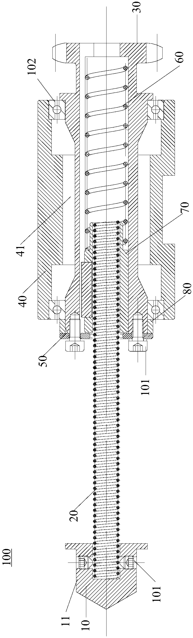
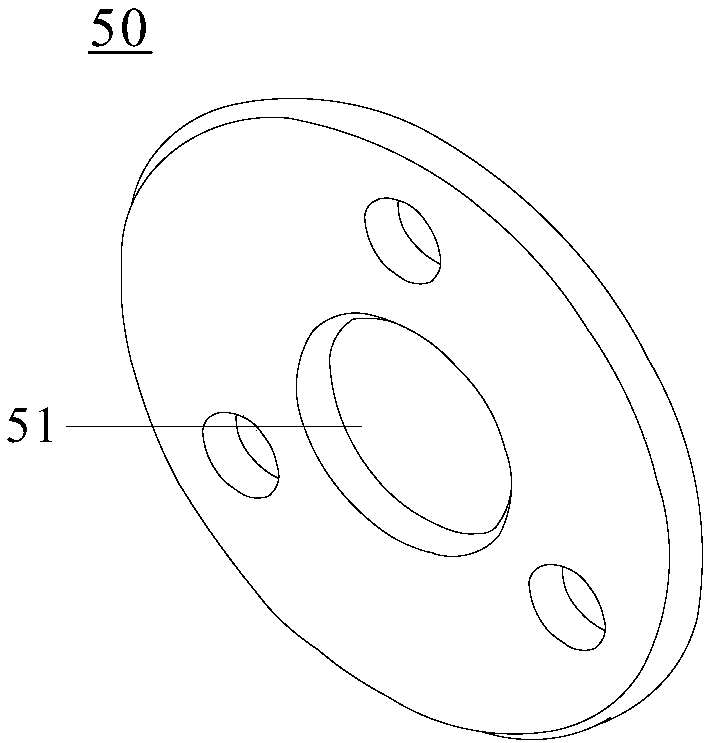
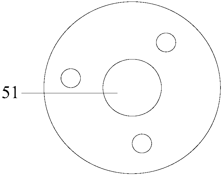
[0056] figure 1 It is a structural schematic diagram of the driving device for the stocker provided in Embodiment 1 of the present invention. figure 2 It is a structural schematic diagram of the gland of the stocker driving device provided by Embodiment 1 of the present invention. image 3 It is a front view of the gland of the stocker driving device provided in the first embodiment of the present invention. Figure 4 It is a side view of a gland of the stocker driving device provided in Embodiment 1 of the present invention. Figure 5 It is a side view of another gland of the stocker driving device provided in Embodiment 1 of the present invention. Figure 6 It is a structural schematic diagram of the driving wheel of the stocker driving device provided in Embodiment 1 of the present invention. Figure 7 It is a structural schematic diagram of the elastic member mounting seat of the stocker driving device provided by Embodiment 1 of the present invention.
[0057] Based ...
Embodiment 2
[0089] On the basis of the first embodiment above, the second embodiment of the present invention also provides a stocker.
[0090] Specifically, the stocker includes multiple stocker driving devices 100 in the first embodiment and multiple stocker steel pipes, multiple drive heads 10 of the stocker drive devices 100 and multiple stocker steel pipes one by one corresponding settings.
[0091] A plurality of stocker steel pipes are parallel to each other and separated by a predetermined distance, and a plurality of stocker driving devices 100 are separated by a predetermined distance, and the axes of the driving wheels 30 of the plurality of stocker driving devices 100 are parallel to each other.
[0092] It should be noted that, when the blank storage device is in operation, the drive head 10 is first embedded in the limiting groove at the end of the steel tube of the blank storage box, and at this time the elastic member 60 is in a compressed state. Next, the output shaft of...
PUM
 Abstract
Description
Claims
Application Information
 - Generate Ideas
- Intellectual Property
- Life Sciences
- Materials
- Tech Scout
- Unparalleled Data Quality
- Higher Quality Content
- 60% Fewer Hallucinations
Browse by: Latest US Patents, China's latest patents, Technical Efficacy Thesaurus, Application Domain, Technology Topic, Popular Technical Reports.
© 2025 PatSnap. All rights reserved.Legal|Privacy policy|Modern Slavery Act Transparency Statement|Sitemap|About US| Contact US: help@patsnap.com