Carbon fiber three-piece combined rim and forming die thereof
A combined rim and forming mold technology, applied in rims, transportation and packaging, vehicle parts, etc., can solve the problems of carbon fiber rim forming difficulties and carbon fiber three-piece combined rim forming difficulties, and achieve feasibility and operability. The effect of high strength and high overall strength
- Summary
- Abstract
- Description
- Claims
- Application Information
AI Technical Summary
Problems solved by technology
Method used
Image
Examples
specific Embodiment approach 1
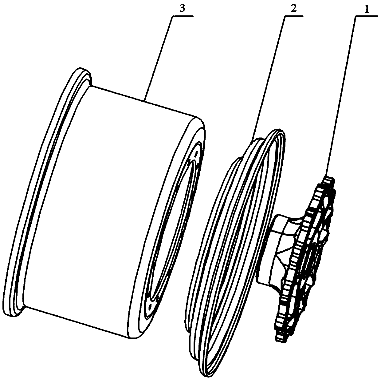
[0026] Specific implementation mode one: as figure 1 As shown, this embodiment discloses a carbon fiber three-piece combined rim, including an inner rim 3, an outer rim 2 and a spoke 1, and the inner end surface of the outer rim 2 and the outer end surface of the inner rim 3 are connected by high-strength glue. The rim body is formed by adhesive sealing fixed connection, the inner end of the spoke 1 is provided with a central boss, the central boss of the spoke 1 is arranged in the center cavity of the rim body, and the spoke 1 is connected with the rim body (through bolts and lock nuts). ) locking connection (the spoke 1, the outer rim 2 and the inner rim 3 are locked and fixed with bolts and lock nuts, and after inspection, the formed rim can be applied to the actual vehicle).
specific Embodiment approach 2
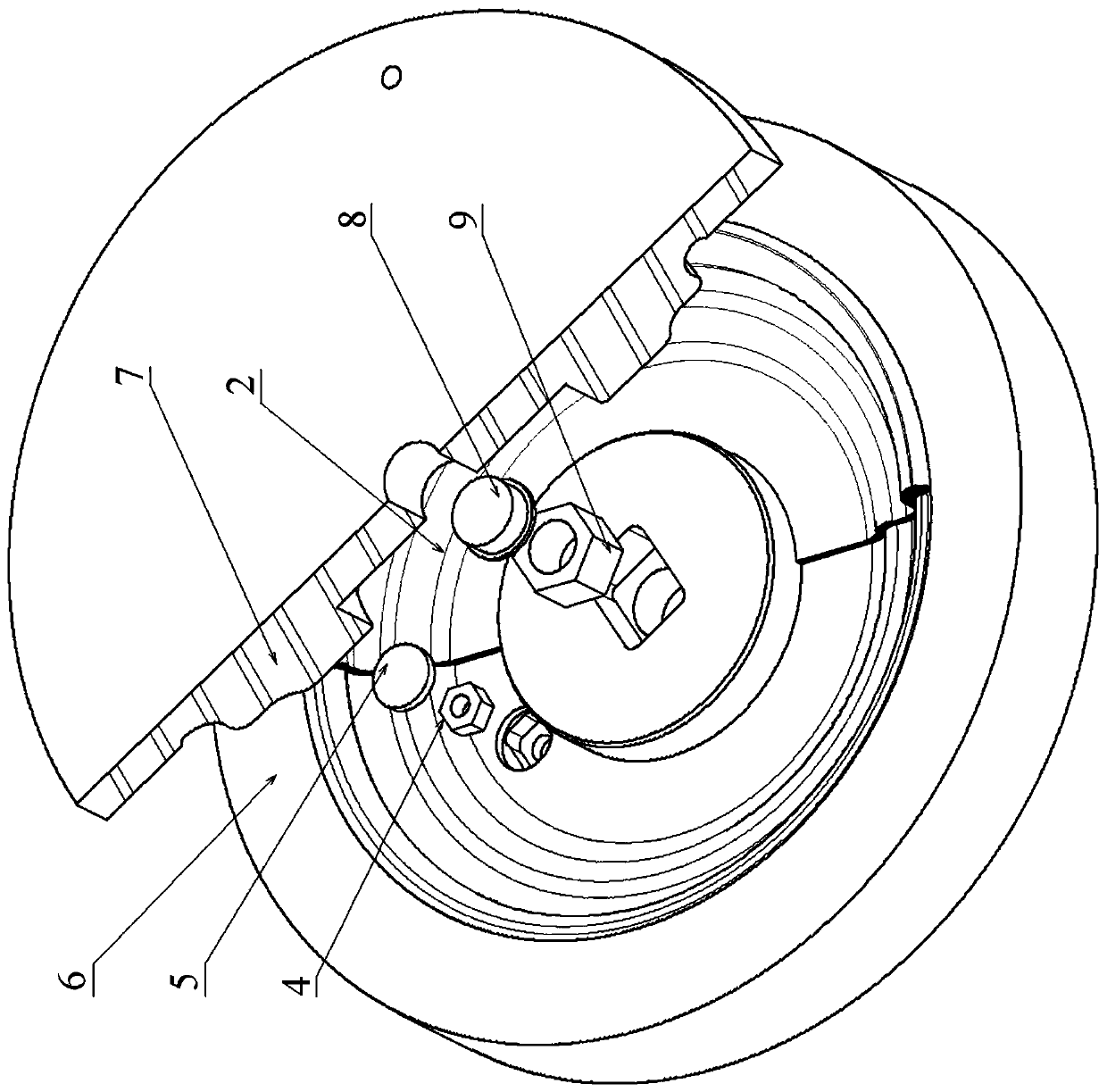
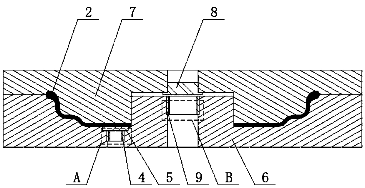
[0027] Specific implementation mode two: as Figure 1-Figure 7 As shown, this embodiment discloses a molding die for a carbon fiber three-piece composite rim described in Embodiment 1, the molding die includes an outer rim die set and an inner rim die set; the outer rim die set and The inner rim mold group is coaxially arranged, and the outer rim mold group includes an upper mold 7, a lower mold 6, a parting block 8, a parting nut 9, a lifting block 5 and a lifting nut 4; the inner rim mold The group includes a mold cover 13, a round tube outer mold 15, a round tube inner core 17, a round cake inner core 18 and a mold bottom 16;
[0028] The lower surface of the upper mold 7 is provided with an annular boss, the annular boss is coaxially arranged with the upper mold 7, the middle part of the annular boss forms a cylindrical groove, and the middle part of the cylindrical groove of the upper mold 7 is provided with a platform. The shoulder through hole is embedded with a partin...
specific Embodiment approach 3
[0030] Specific implementation mode three: as figure 2 , image 3 As shown, this embodiment is a further description of the second specific embodiment. The lower end surface of the upper mold 7 is located on the non-forming surface and is provided with a positioning through hole 1, and the upper end surface of the lower mold 6 is located on the non-forming surface. There are two positioning through holes. The first positioning through hole is coaxial with the second positioning through hole and has the same diameter. Alignment (Considering the valve protruding, the alignment must be ensured when the upper and lower molds are closed, by inserting cylindrical pins into the positioning through hole 2 of the lower mold 6 and the positioning through hole 1 of the upper mold 7 to ensure the alignment of the upper and lower molds when closing the molds) .
PUM
 Abstract
Description
Claims
Application Information
 - R&D
- Intellectual Property
- Life Sciences
- Materials
- Tech Scout
- Unparalleled Data Quality
- Higher Quality Content
- 60% Fewer Hallucinations
Browse by: Latest US Patents, China's latest patents, Technical Efficacy Thesaurus, Application Domain, Technology Topic, Popular Technical Reports.
© 2025 PatSnap. All rights reserved.Legal|Privacy policy|Modern Slavery Act Transparency Statement|Sitemap|About US| Contact US: help@patsnap.com


