
Rapid charging device of new energy automobile

A new energy vehicle and fast charging technology, applied in electric vehicle charging technology, charging stations, electric vehicles, etc., can solve the problems of high production cost of charging piles, reduce space utilization, increase occupied area, etc., and improve the plugging efficiency. , The effect of reducing personnel operations and improving utilization

Active Publication Date: 2019-09-20
泰州新滨江智慧科技服务有限公司
View PDF9 Cites 2 Cited by
  • Summary
  • Abstract
  • Description
  • Claims
  • Application Information

AI Technical Summary

Problems solved by technology

[0003] Electric vehicles will use charging piles when charging, but the existing charging piles are expensive to manufacture. How to quickly insert the charging head into the charging pile automatically to complete the automatic charging connection and improve charging safety has become an important issue
[0004] The comparison document CN201710241393.9 records a fast charging device for new energy vehicles. When the device is in use, the charging head can be quickly inserted into the charging pile, but there may be reverse insertion between the charging head and the electric jack. , and prone to fall off
[0005] In addition, most of the existing charging piles can only charge one car at a time, which relatively increases the occupied area and reduces the space utilization rate.

Method used


Image

  • Rapid charging device of new energy automobile
  • Rapid charging device of new energy automobile
  • Rapid charging device of new energy automobile

Examples


Embodiment Construction

[0028] The following examples are for illustrative purposes only and are not intended to limit the scope of the invention.

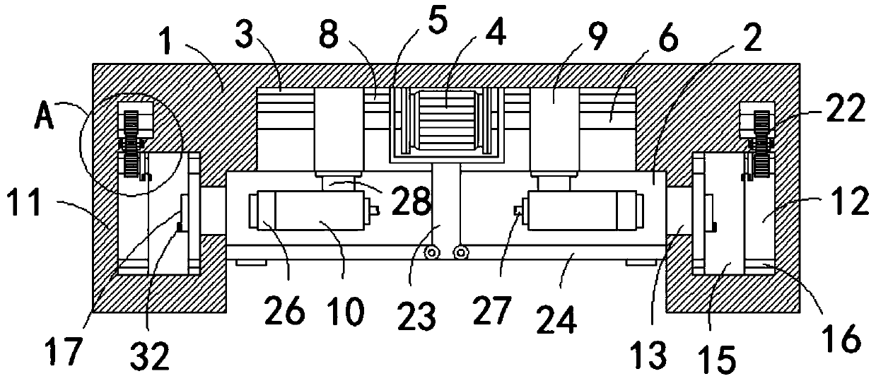
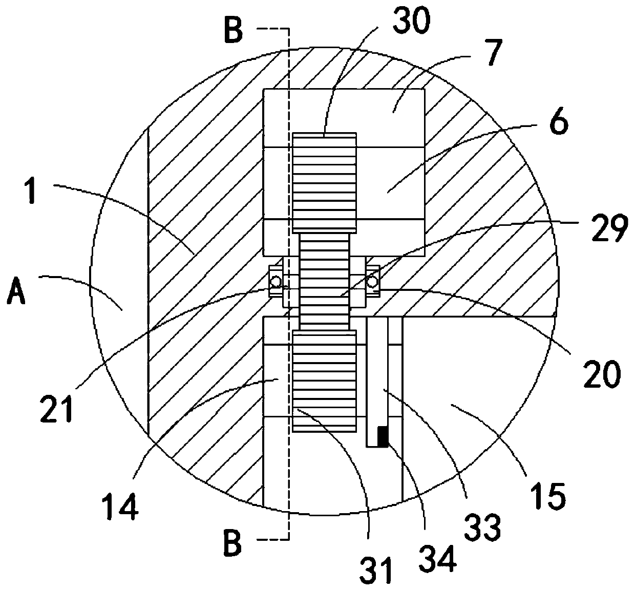
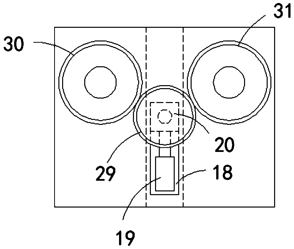
[0029] Such as Figure 1-6 As shown, a fast charging device for new energy vehicles includes a charging pile body 1, a first groove 2 is opened on the front side wall of the charging pile body 1, and a first groove 2 is opened on the inner wall of the first groove 2 to communicate with it. The second groove 3, the side wall of the second groove 3 is fixedly connected with a biaxial motor 4, the outer side of the biaxial motor 4 is fixedly sleeved with a square frame 5, and the two output ends of the biaxial motor 4 are respectively fixedly connected with The first threaded rod 6, the inner wall of the second groove 3 is provided with a circular groove 7 corresponding to the position of the first threaded rod 6, and the end of the first threaded rod 6 away from the biaxial motor 4 and the circular groove 7 The inner wall of the square frame 5 is rotatabl...


PUM


Abstract

The invention belongs to the technical field of new energy automobile charging, and particularly relates to a rapid charging device of a new energy automobile. The rapid charging device comprises a charging pile body. A first groove is formed in the front side wall of the charging pile body. A second groove communicating with the first groove is formed in the inner wall of the first groove. A double-shaft motor is fixedly connected to the side wall of the second groove. A square frame fixedly sleeves the outer side of the double-shaft motor. The two output ends of the double-shaft motor are respectively and fixedly connected with a first threaded rod. Circular grooves corresponding to the positions of the first threaded rods are formed in the inner wall of the second groove. One ends, far away from the double-shaft motor, of the first threaded rods are rotationally connected with the inner walls of the circular grooves. Horizontal limiting rods are fixedly connected to the left side wall and right side wall of the square frame correspondingly. The rapid charging device has the advantages that charging plug-in work can be automatically controlled and the rapid charging device can be simultaneously used for two electric automobiles, so that the space utilization rate is increased.

Description

technical field [0001] The invention belongs to the technical field of new energy vehicle charging, and in particular relates to a fast charging device for new energy vehicles. Background technique [0002] Electric vehicles are non-polluting, do not emit carbon dioxide, and have no tail gas pollution. For ordinary cars with high carbon dioxide emissions, they have the advantages of energy saving and environmental protection. At the same time, they are quite beneficial for controlling environmental pollution and reducing exhaust emissions. [0003] Electric vehicles will use charging piles when charging, but the existing charging piles are expensive to manufacture. How to quickly insert the charging head into the charging pile automatically to complete the automatic charging connection and improve charging safety has become an important issue. [0004] The comparison document CN201710241393.9 records a fast charging device for new energy vehicles. When the device is in use, ...

Claims


Application Information

Patent Timeline
Patent Type & Authority Applications(China)
IPC IPC(8): B60L53/31B60L53/16
CPCB60L53/16B60L53/31Y02T10/70Y02T10/7072Y02T90/12Y02T90/14
Inventor 戴陈莲
Owner 泰州新滨江智慧科技服务有限公司
Learn More