Mounting method of torsion bar component and torsion bar component mounting structure

An installation method and torsion bar technology, which is applied in the field of anti-roll torsion bar system installation, can solve problems such as high cost and complex structure, and achieve the effects of easy connection, high compact structure, and small space occupancy rate of the connection structure

Active Publication Date: 2019-09-20
ZHUZHOU TIMES NEW MATERIALS TECH
View PDF7 Cites 3 Cited by
  • Summary
  • Abstract
  • Description
  • Claims
  • Application Information

AI Technical Summary

Problems solved by technology

[0006] However, for the torsion bar system where the torsion bar axis traverses the frame beam structure, no matter what kind of structure the support seat is, its structure is usually more complicated and the cost is higher

Method used


Image

  • Mounting method of torsion bar component and torsion bar component mounting structure
  • Mounting method of torsion bar component and torsion bar component mounting structure
  • Mounting method of torsion bar component and torsion bar component mounting structure

Examples


Embodiment Construction

[0030] Combine below Figure 1 to Figure 5 The embodiments of the present invention will be described in detail.

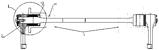
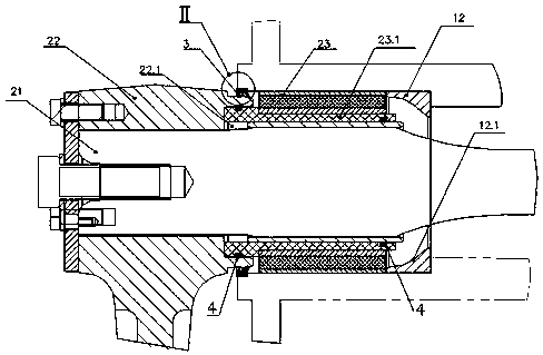
[0031] The installation method of the torsion bar assembly is characterized in that the installation hole 11 corresponding to the torsion bar assembly 2 is processed on the frame 1 of the bogie, the torsion bar assembly 2 is traversed in the installation hole 11 and the torsion bar assembly 2 is installed with the torsion bar assembly. The holes 11 are connected by interference fit, and a stop 12 for axially limiting the torsion bar assembly 2 is provided in the installation hole 11 , and the stop 12 is in close contact with the torsion bar assembly 2 .

[0032] Such as figure 1 As shown, the installation hole 11 corresponding to the torsion bar assembly 2 is processed on the frame 1 of the bogie, and the torsion bar assembly 2 and the installation hole 11 are connected by interference fit, that is, the torsion bar assembly 2 is directly installed on the frame, s...


PUM


Abstract

A mounting method of a torsion bar component is characterized in that a mounting hole corresponding to the torsion bar component is machined in a framework of a bogie; the torsion bar component transversely penetrates through the mounting hole, and the torsion bar component is connected with the mounting hole in the form of interference fit; a stopper used for axially limiting the torsion bar component is arranged in the mounting hole; and the stopper is in contact with the torsion bar component in an abutting manner. According to the mounting method of the torsion bar component, as the torsion bar component is directly mounted on the framework, a supporting seat component in an anti-roll torsion bar system is eliminated, the structure of an anti-roll torsion bar component is simplified, the production cost is reduced, the use reliability of the torsion bar component is not affected in the case of guaranteeing that the supporting seat component is eliminated, the connection between the torsion bar component and the framework is easy to realize, the connecting mode is simpler, the labor intensity of mounting the torsion bar component on the framework can be effectively reduced, and moreover, the space occupancy rate of the a connecting structure between the torsion bar component and the framework is small, and the structural compactness of the connecting structure between the torsion bar component and the framework is high. The invention further provides a torsion bar component mounting structure.

Description

technical field [0001] The invention relates to an installation method of a torsion bar assembly and an installation structure of the torsion bar assembly, belonging to the technical field of anti-rolling torsion bar system installation. Background technique [0002] The existing anti-roll torsion bar system for rail transit generally includes three parts: torsion bar assembly, connecting rod assembly and support seat assembly. The torsion bar assembly is fixed on the frame through the support seat assembly, and fixed on the vehicle body through the connecting rod assembly. When a roll occurs between the vehicle body and the frame, the torsion bar assembly prevents the increase of the roll angle of the vehicle body relative to the frame, thereby suppressing the roll of the vehicle and improving the lateral stability of the vehicle. The support seat assembly fixed on the frame is connected to the torsion bar shaft in the torsion bar assembly through a layered support ball joi...

Claims


Application Information

Patent Timeline
Patent Type & Authority Applications(China)
IPC IPC(8): B61F5/24B61F5/52
CPCB61F5/24B61F5/52
Inventor 聂清明邹敏佳张维亨倪世锋李鹏王亚平刘文松杜方孟
Owner ZHUZHOU TIMES NEW MATERIALS TECH
Why Eureka
Try Eureka