Method for connecting copper-based alloy and die steel alloy by 3D printing method

A copper-based alloy, 3D printing technology, applied in the field of 3D printing, can solve the problem of high cost of random cooling molds, and achieve high social and economic benefits, improve production efficiency and service life.

Inactive Publication Date: 2019-09-20
哈特三维(中山)金属材料有限公司
View PDF18 Cites 5 Cited by
  • Summary
  • Abstract
  • Description
  • Claims
  • Application Information

AI Technical Summary

Problems solved by technology

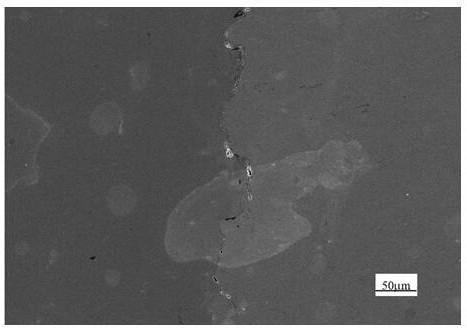
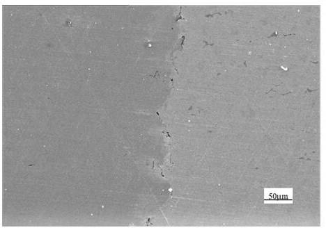
[0004] The purpose of the present invention is to solve the problem that the current copper-based alloy cannot be used to manufacture a random cooling mold and the cost of using MS1 mold steel alloy to manufacture a random cooling mold is high, and to provide a copper-based alloy using a 3D printing method. A method for connecting with a mold steel alloy, which can realize seamless connection and the connection interface has good mechanical properties, and the manufactured conformal cooling mold can be used in actual production

Method used


Image

  • Method for connecting copper-based alloy and die steel alloy by 3D printing method
  • Method for connecting copper-based alloy and die steel alloy by 3D printing method
  • Method for connecting copper-based alloy and die steel alloy by 3D printing method

Examples


specific Embodiment approach 1

[0018] Specific implementation mode 1: This implementation mode records a method for realizing the connection between copper-based alloy and mold steel alloy by using 3D printing method, and the steps of the method are as follows:

[0019] Step 1: Make a copper-based alloy base according to actual needs. It is necessary to ensure that the surfaces on the base that will be connected to the mold steel are on the same plane, and use thermal spraying technology on the surface that will be connected to the mold steel on the base. A layer of nickel is plated; the copper-based alloy base can be processed by traditional machining or casting technology;

[0020] Step 2: Use EOS M280 3D printer to sinter the nickel-plated surface, and polish the sintered nickel-plated surface into a plane;

[0021] Step 3: Use 3D printing technology to print out prints with different shape requirements on the base according to actual needs;

[0022] Step 4: Heat treatment on the manufactured parts.

specific Embodiment approach 2

[0023] Embodiment 2: In Embodiment 1, a 3D printing method is used to realize the connection between copper-based alloy and die steel alloy. In step 1, the thickness of the nickel plating layer is 20-40 μm.

specific Embodiment approach 3

[0024] Specific embodiment three: a method of using a 3D printing method to realize the connection between the copper-based alloy and the mold steel alloy described in the specific embodiment one. In step two, the sintering treatment is specifically: using SLM technology to perform laser sintering treatment, The laser power is 300W, the scanning rate is 960mm / s, the scanning distance is 0.11mm, and the number of laser scanning is 2 times.

[0025] Specific embodiment four: a method of using 3D printing method to realize the connection between copper-based alloy and die steel alloy described in specific embodiment one, in step three, the powder used for printing is MS1 die steel powder, and the printing parameters are: The powder thickness is 40μm, the scanning speed is 960mm / s, the printing power of the first and second layers is 265~325W, and each layer is scanned twice by laser, starting from the third layer, the printing power is 285W, and the laser scans once until the prin...


PUM


Abstract

The invention provides a method for connecting copper-based alloy and die steel alloy by a 3D printing method, and belongs to the technical field of 3D printing. The method comprises the following steps: processing a copper-based alloy base which is to be connected and meets conditions through traditional technologies such as the casting technology and the mechanical processing technology; spraying a pure nickel layer on the surface to be printed of the copper-based alloy base by a plasma spraying method; sintering; grinding until the surface to be printed of the base is flat; performing 3D printing on the treated base by a 3D technology, wherein the printing material is die steel alloy powder; moving out a printed part which is connected to a base plate after printing; and thermally processing to obtain a finished product. With the adoption of the method, the high heat conductivity of the copper-based alloy and the high mechanical performance of the die steel alloy are integrated, so that the production efficiency of a shape follow-up cooling die can be effectively improved, and the service life of the shape follow-up cooling die is effectively prolonged; and the method has important social and economic benefits.

Description

technical field [0001] The invention belongs to the technical field of 3D printing, and in particular relates to a method for realizing the connection of a copper-based alloy and a mold steel alloy by using a 3D printing method. Background technique [0002] The cooling system of the injection mold affects the quality and production efficiency of the molded product. The traditional cooling system is difficult to achieve uniform cooling of the mold, and the molded product is prone to defects such as warping and uneven shrinkage. The cooling water channel of the accompanying cooling mold is changed according to the shape of the product, which can achieve uniform cooling of each part of the product, significantly improve the quality of the product, reduce the cooling time, and has strong practicability, but the traditional processing method is not suitable for processing the accompanying cooling water channel . As a kind of additive manufacturing, selective laser melting (SLM)...

Claims


Application Information

Patent Timeline
IPC IPC(8): C23C4/06B22F3/105B22F3/24B33Y10/00
CPCC23C4/06B22F3/24B33Y10/00B22F2003/248B22F10/00B22F10/28B22F10/36B22F10/64B22F10/366Y02P10/25
Inventor 骆良顺刘桐谢春林董定平彭泽丛陈大勇秦东
Owner 哈特三维(中山)金属材料有限公司
Why Eureka
Try Eureka