
Lifting and drilling integrated machine

An all-in-one machine and drilling mechanism technology, which is applied to cranes, earthwork drilling, drilling equipment, etc., can solve problems such as low hoisting efficiency, increased mechanical shifts, and inconvenient mechanical transitions, so as to improve safety and work efficiency. The effect of reducing installation space and reducing manual participation

Inactive Publication Date: 2019-09-20
JIANGSU ELECTRIC POWER CO +2
View PDF9 Cites 3 Cited by
  • Summary
  • Abstract
  • Description
  • Claims
  • Application Information

AI Technical Summary

Problems solved by technology

[0003] At present, as a new type of construction equipment for line pile foundations, rotary drilling rigs have the advantages of fast drilling speed, good hole quality, and high degree of mechanization. Higher, for the southern region, the distribution of river network terrain is more, the entry of rotary drilling rigs is limited by the bearing capacity of the foundation of rural roads and the weight limit of bridges, the mechanical transfer is inconvenient, and a lot of preliminary work for temporary road construction (steel plate paving) is required , the transition between towers is slow
For the steel cage hoisting process, rotary drilling rigs and submersible drilling rigs use their own drilling rig platforms (tripod, gantry) for hoisting, which has low hoisting efficiency and poor safety; when using rotary drilling rigs for drilling, usually On-site equipment A crane is used to hoist the steel cage, which increases the number of mechanical shifts in the limited construction site, making construction management difficult, and also increases the overall mechanical cost of foundation construction

Method used


Image

  • Lifting and drilling integrated machine
  • Lifting and drilling integrated machine
  • Lifting and drilling integrated machine

Examples


Embodiment Construction

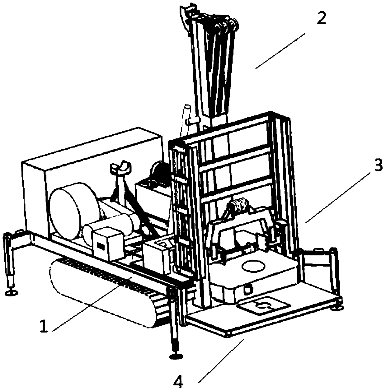
[0019] In order to make the purpose, technical solutions and advantages of the present invention clearer, the following in conjunction with specific examples, and with reference to the appended Figure 1-4 , to further describe the present invention in detail.

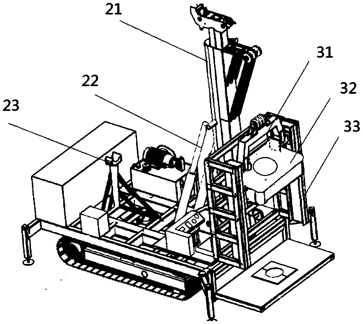
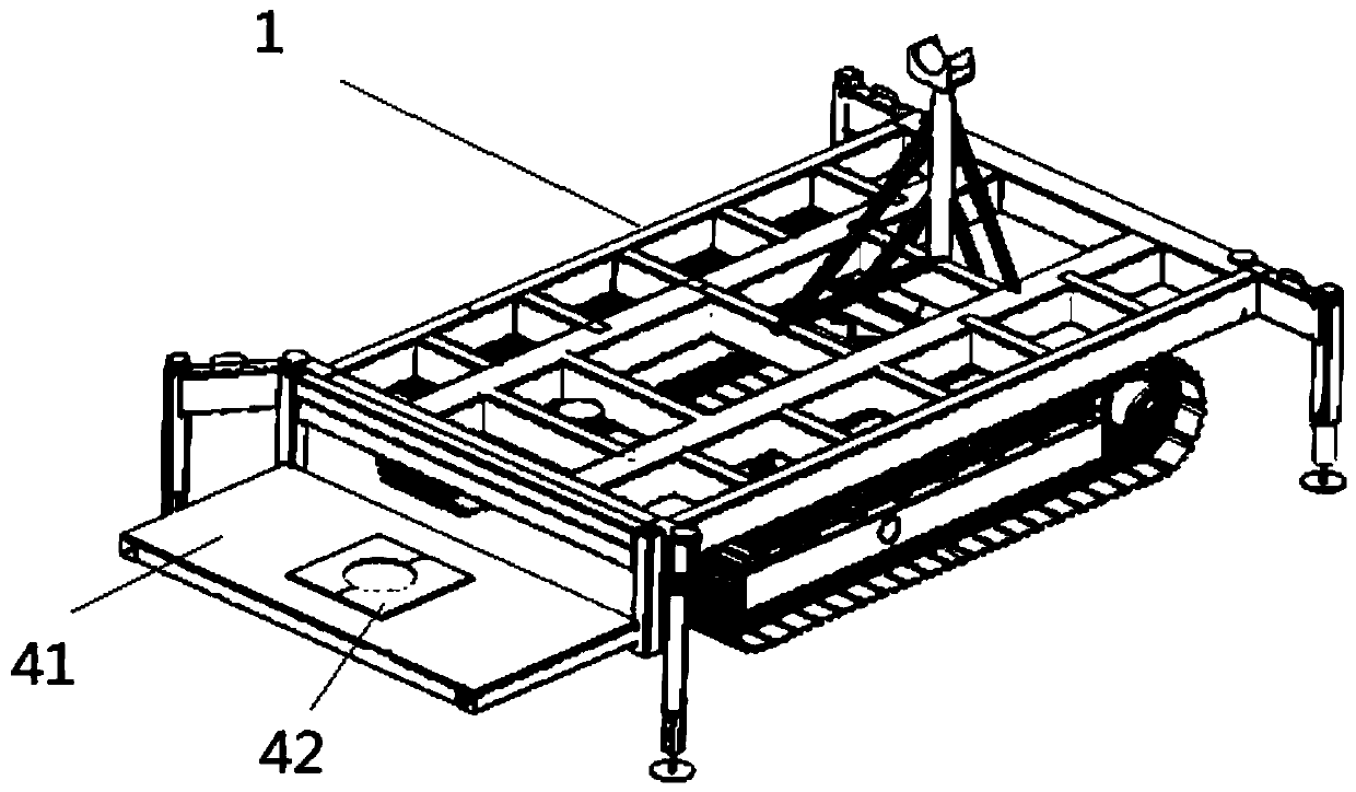
[0020] In one embodiment of the present invention, the integrated hanging and drilling machine includes: an underframe 1 , a lifting mechanism 2 , a drilling mechanism 3 , a wellhead plate mechanism 4 , and a slewing mechanism.

[0021] Underframe 1 is used as the skeleton of the whole machine, and is used for installing all assemblies and components, so that the whole machine becomes a whole.

[0022] In one embodiment, the crane-drilling machine includes a walking device, which is used to support the body, and convert the driving torque and rotational motion transmitted from the engine to the driving wheels into the driving force and forward and backward motion required for the work and travel of the tracked vehicle....


PUM


Abstract

The invention provides a lifting and drilling integrated machine, which comprises an underframe, a lifting mechanism, a drilling mechanism, a drilling template mechanism and a rotating mechanism. The drilling template mechanism comprises a drilling template main body, and a clamping ring located on the drilling template main body; the diameter of the clamping ring is smaller than that of a spiral joint of a drill rod, and thus during drilling operation of the lifting and drilling integrated machine, the clamping ring can clamp the spiral joint of the drill rod; and the drilling template mechanism and the underframe are connected in a pivotal mode. The lifting and drilling integrated machine integrates the double effects of lifting and drilling, meanwhile, a drilling template of the integrated machine is provided with the drill rod clamping ring, thus manual participation can be reduced, and the safety and working efficiency are improved; and meanwhile, the drilling template is arranged to be able to rotate around the underframe in a pivotal mode, thus the mounting space during transportation of the lifting and drilling integrated machine is reduced, and the lifting and drilling integrated machine can meet construction requirements of various different sites.

Description

technical field [0001] The invention relates to the field of construction machinery, in particular to an integrated drilling machine. Background technique [0002] In recent years, with the rapid development of my country's economy and society, the scale of power grid construction has continued to increase, and the mechanized construction technology of transmission line engineering has been further developed. In the foundation construction of overhead transmission lines at this stage, bored pile foundations have been widely used. The cast-in-situ pile foundation is the undisturbed soil foundation. Compared with the stepped foundation, it has the advantages of good environmental protection, less labor, and high bearing capacity of the pile foundation. Today, with the deepening of construction technology, it is widely adopted and used by construction parties. [0003] At present, as a new type of construction equipment for line pile foundations, rotary drilling rigs have the ad...

Claims


Application Information

Patent Timeline
IPC IPC(8): E21B7/02E21B15/00B66C23/36
CPCB66C23/36E21B7/02E21B7/026E21B15/00
Inventor 丁道军陆东生潘峰杨兵舒邦京刘强高歌王子羲段永海甄文媛李子麟许强郭越红
Owner JIANGSU ELECTRIC POWER CO
Learn More