Oil separation device, compressor and vehicle with compressor

A technology for oil separation and compressors, which is applied to vehicle parts, parts of pumping devices for elastic fluids, mechanical equipment, etc. It can solve the problem of affecting the space size of refrigeration devices, failing to meet the oil-gas separation effect, and the cost of rotary compressors. Advanced problems, to achieve the effect of good practicability, small footprint and simple structure

Pending Publication Date: 2019-09-20
GUANGDONG WELLING AUTO PARTS CO LTD
View PDF0 Cites 2 Cited by
  • Summary
  • Abstract
  • Description
  • Claims
  • Application Information

AI Technical Summary

Problems solved by technology

However, this oil-gas separation method has a better separation effect on low-pressure and low-density refrigerants such as R22 and R134a. When the rotary compressor uses high-pressure and high-tightness refrigerants such as R410A and R744, the separation effect is poor. This is because the refrigerant The increase in sealing and speed makes it more capable of carrying oil. The centrifugal force of the above-mentioned oil-gas separation method can no longer meet the oil-gas separation effect; moreover, the above-mentioned oil-gas separation method relies on the large cavity inside the shell to achieve the settlement of oil mist, resulting in Rotary compressors have higher cost and larger dimensions, which affect the space size of refrigeration equipment such as air conditioners

Method used


Image

  • Oil separation device, compressor and vehicle with compressor
  • Oil separation device, compressor and vehicle with compressor
  • Oil separation device, compressor and vehicle with compressor

Examples


Embodiment 1

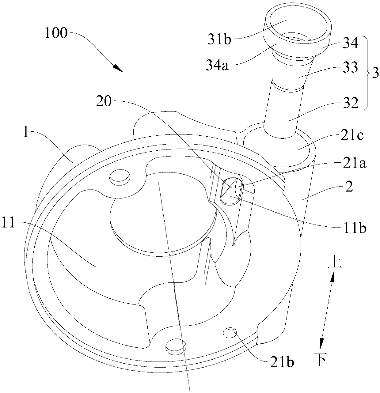
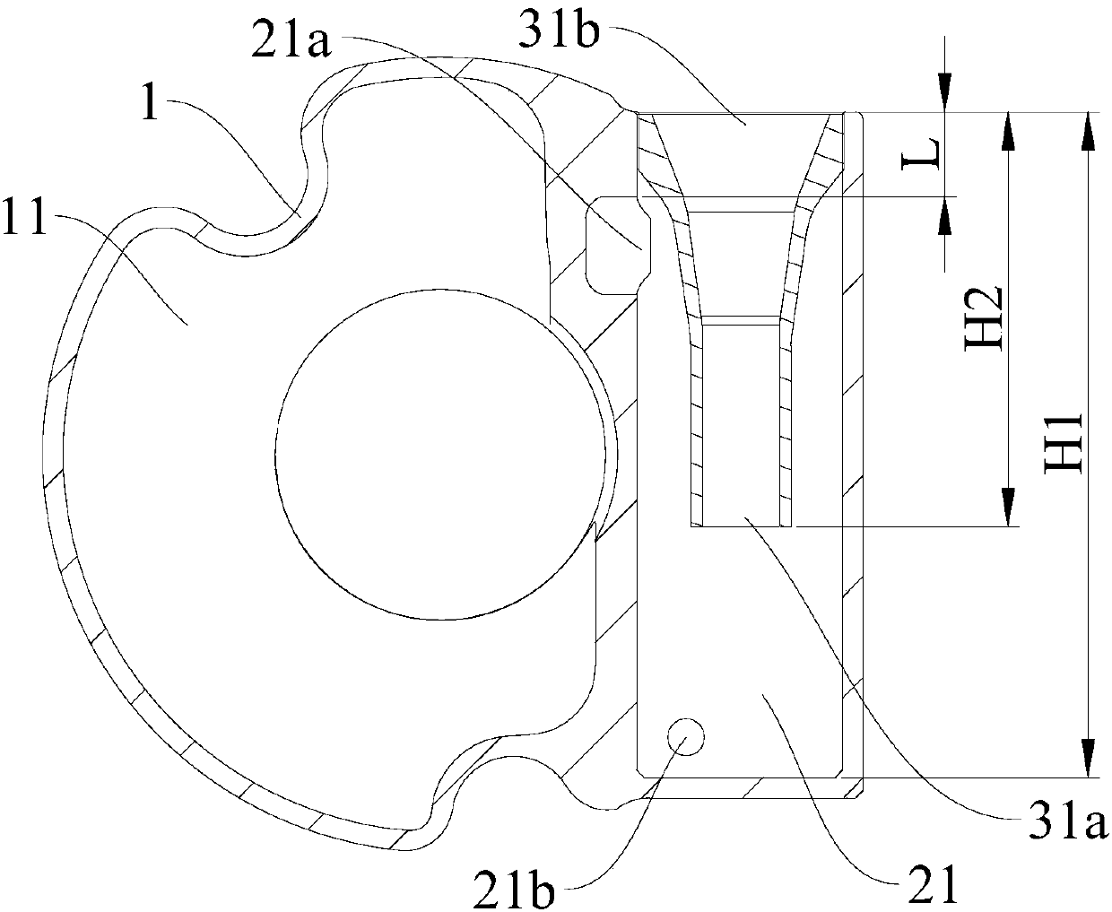
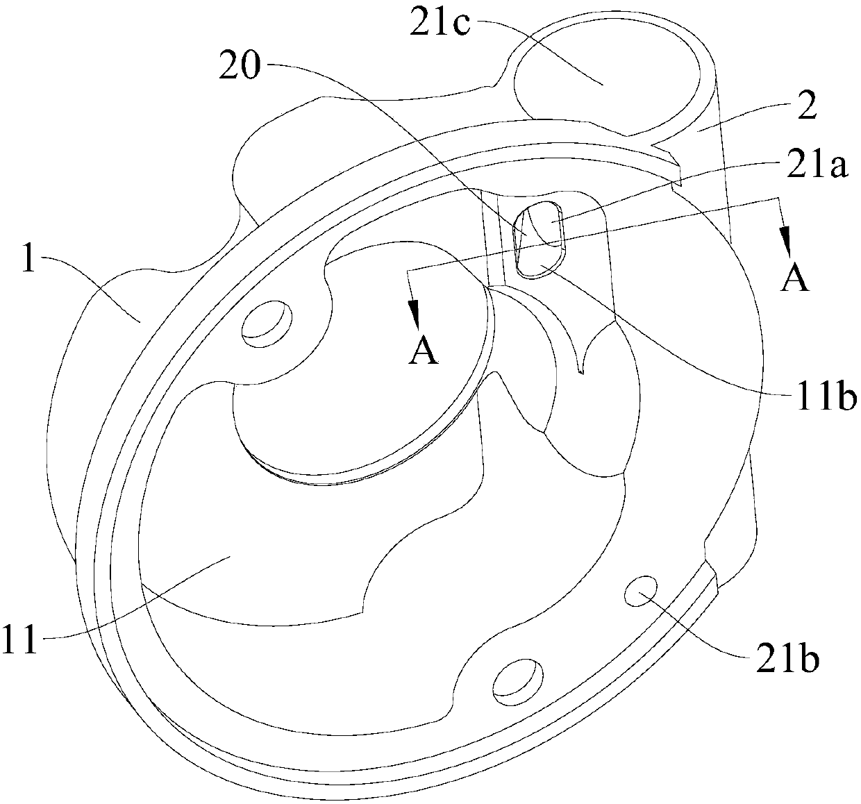
[0087] In this example, if Figure 1-Figure 5As shown, the oil separation device 100 includes a first housing 1 , a second housing 2 and an oil separation insert 3 . A first chamber 11 is defined in the first housing 1, and a first air inlet 11a and a first air outlet 11b communicating with the first chamber 11 are formed on the inner wall of the first housing 1. The first air inlet 11a is located on one axial side of the first housing 1, and the other axial side of the first housing 1 is closed; the second housing 2 is arranged on the outer wall of the first housing 1, and the second housing 2 defines a The second chamber 21 and the volume of the second chamber 21 is smaller than the volume of the first chamber 11, the second housing 2 is provided with an air inlet passage 20 to communicate with the first chamber 11 and the second chamber 21, the second A second air inlet 21a and an oil discharge port 21b communicating with the second chamber 21 are formed on the inner wall ...

Embodiment 2

[0094] Such as Image 6 As shown, the structure of this embodiment is substantially the same as that of Embodiment 1, wherein the same components use the same reference numerals, the difference is that: the intake passage 20 is provided on the first housing 1 to communicate with the first chamber 11 and the second chamber 21.

Embodiment 3

[0096] Such as Figure 7 As shown, the structure of this embodiment is substantially the same as that of Embodiment 1, wherein the same components use the same reference numerals, the difference is that: the first pipe section 32 and the third pipe section 34 are generally formed in a cylindrical shape, the first The cross-sectional area of ​​the pipe section 32 is smaller than the cross-sectional area of ​​the third pipe section 34, and the second pipe section 33 is roughly formed as a conical cylinder; the angle between the central axis of the second housing 2 and the rotation axis of the crankshaft 102 is a non-right angle, for example, The central axis of the second housing 2 may be arranged parallel to the rotation axis of the crankshaft 102 .


PUM


Abstract

The invention discloses an oil separation device, a compressor and a vehicle with the compressor. The oil separation device comprises a first shell, a second shell and an oil separation insertion pipe, wherein the first shell is internally provided with a first chamber, and the first shell is provided with a first air inlet communicating with the first chamber; the second shell is arranged on the first shell, the second shell is internally provided with a second cavity, the inner wall of the second cavity is provided with a second air inlet, and the second cavity is provided with an oil discharge opening; and the oil separation insertion pipe is arranged in the second cavity, and an exhaust channel communicating with the second cavity is arranged in the oil separation insertion pipe. According to the oil separation device, the air flow noise is reduced, oil-gas separation and oil recovery are realized, the structure is simple, the occupied space is small, so that when the oil separation device is applied to the compressor, the design of miniaturization, low noise and low oil discharge capacity of the compressor can be realized.

Description

technical field [0001] The invention relates to the technical field of refrigeration equipment, in particular to an oil separation device, a compressor and a vehicle with the same. Background technique [0002] In the related technology, the refrigerant in the rotary compressor is compressed and discharged into the muffler for preliminary noise reduction, and then discharged into the shell of the rotary compressor, and the oil and gas are separated under the action of centrifugal force through the rotation and stirring of the motor rotor. Then it flows into a larger buffer space to reduce the flow velocity of the airflow and realize the settlement of the oil mist in the refrigerant. However, this oil-gas separation method has a better separation effect on low-pressure and low-density refrigerants such as R22 and R134a. When the rotary compressor uses high-pressure and high-tightness refrigerants such as R410A and R744, the separation effect is poor. This is because the refri...

Claims


Application Information

Patent Timeline
Patent Type & Authority Applications(China)
IPC IPC(8): F04C18/356F04C23/00F04C29/02F04C29/06F04C29/12B60H1/32
CPCB60H1/3223F04C18/3562F04C23/001F04C29/026F04C29/06F04C29/12
Inventor 杨开成黎法运虞阳波
Owner GUANGDONG WELLING AUTO PARTS CO LTD
Why Eureka
Try Eureka