Rotational positioning mechanism and upper limb rehabilitation device with mechanism

A technology of positioning mechanism and positioning plate, which is applied in the direction of pivot connection, passive exercise equipment, physical therapy, etc., can solve the problems of inaccurate positioning and easy sliding, achieve good stability and convenience, and realize automatic locking function Effect

Inactive Publication Date: 2019-09-20
BEIJING INSTITUTE OF PETROCHEMICAL TECHNOLOGY +1
View PDF6 Cites 3 Cited by
  • Summary
  • Abstract
  • Description
  • Claims
  • Application Information

AI Technical Summary

Problems solved by technology

[0004] The purpose of the present invention is to provide a rotary positioning mechanism for rehabilitation training to solve the technical problem that the rotary positioning mechanism cannot be positioned accurately and is easy to slide in the prior art

Method used


Image

  • Rotational positioning mechanism and upper limb rehabilitation device with mechanism
  • Rotational positioning mechanism and upper limb rehabilitation device with mechanism
  • Rotational positioning mechanism and upper limb rehabilitation device with mechanism

Examples


Embodiment 1

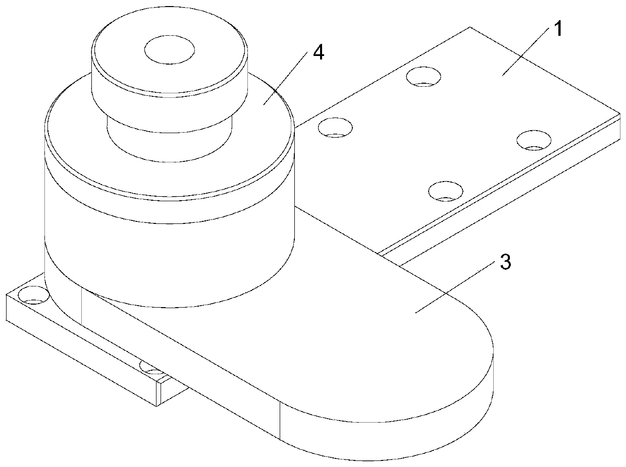
[0044] Such as Figure 1-5 As shown, the present invention provides a rotary positioning mechanism, which mainly includes four parts: a shaft 1, a fixed assembly 2, a rotating assembly 3 and a locking assembly 4, wherein the shaft 1 is fixedly connected to the fixed assembly 2, and the rotating assembly 3 is sleeved on the outside of the shaft 1 and rotates around the shaft 1. A locking assembly 4 is movable on the shaft 1. The locking assembly 4 will not rotate with the rotation of the shaft 1. Therefore, when the rotating assembly 3 rotates to a certain angle , the locking component 4 will be connected to the rotating component 3 by plugging in so as to lock the rotating component 3 .

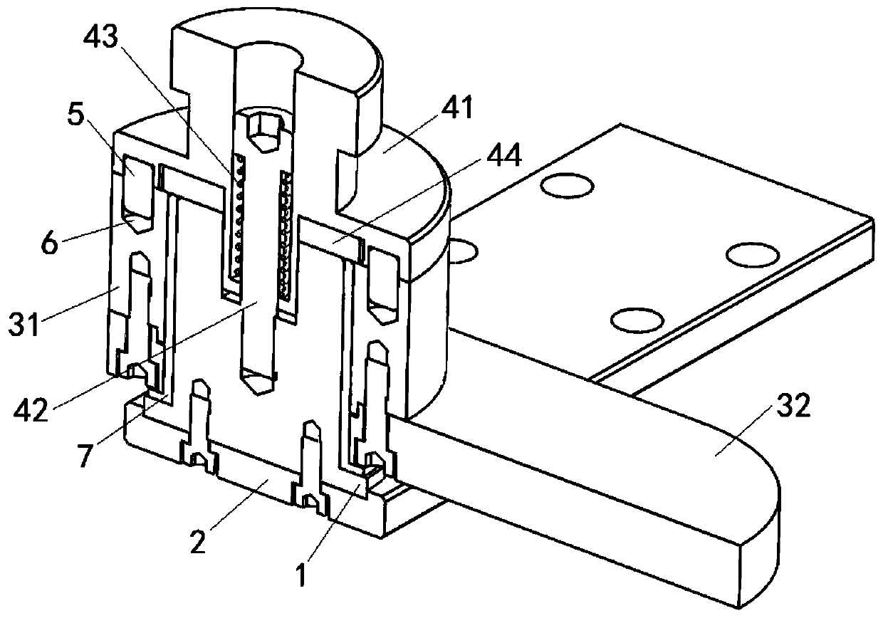
[0045] Specifically, the side of the locking assembly 4 facing the rotating assembly 3 is a positioning pin 5, and the rotating assembly 3 is provided with a pin hole 6. When the pin hole 6 moves below the positioning pin 5 with the rotation of the rotating assembly 3, the locking The assemb...

Embodiment 2

[0063] The difference between this embodiment 2 and embodiment 1 is that a pin hole 6 is provided on the lower surface of the locking assembly 4 and the rotating assembly 3, and a positioning pin matching the pin hole 6 is provided on the upper surface of the rotating assembly 3. 5, whose structure is as Figure 6 shown.

[0064] When the rotary positioning mechanism is working, it is necessary to pull the gland 41 upwards. At this time, the positioning pin 5 is separated from the rotating assembly 3, and the rotating assembly 3 can rotate freely; then the gland 41 is released, and the internal spring generates a pulling force to drive the gland 41 towards the rotating assembly. When the rotating assembly 3 turns to the positioning pin 5 and the pin hole 6 is just aligned, the spring drives the gland 41 to continue to move so that the positioning pin 5 is inserted into the pin hole 6, thereby realizing automatic and precise locking. Specific workflow such as image 3 shown. ...


PUM


Abstract

The invention provides a rotational positioning mechanism and an upper limb rehabilitation device with the mechanism, relates to the technical field of rehabilitation training instruments, and mainly aims to solve the technical problems that a rotational positioning mechanism in a traditional positioning device cannot be posited accurately and is easy to slide. The rotational positioning mechanism comprises a fixing assembly and a rotating assembly in pivot joint through a shaft, wherein the rotating assembly is arranged on the peripheral side of the shaft in a sleeving way; a locking assembly capable of moving up and down along an axis direction of the shaft is arranged on the shaft; and when the locking assembly is acted upon by an external force so as to move toward a direction far away from the rotating assembly, the plug connection of the locking assembly and the rotating assembly can be cancelled so as to relieve the locking of the locking assembly on the rotating assembly, so that the rotating assembly can rotate relative to the fixing assembly. The locking assembly comprises a gland, a positioning plate, a guiding screw and an elastic piece; the gland moves along a length direction of the guiding screw under the actions of the elastic piece and the external force, so that the locking on the rotating assembly is realized; and the positioning plate is used for limiting the gland from rotating.

Description

technical field [0001] The invention relates to the technical field of rehabilitation training equipment, in particular to a rotation positioning mechanism. Background technique [0002] Rehabilitation exercise training machine is an instrument used to train human muscles, especially for people with multiple sclerosis, stroke and hemiplegia, rheumatism, paraplegia and quadriplegia, Parkinson's syndrome, muscle weakness, craniocerebral injury, stroke Patients with diseases such as cardiovascular disease and cardiovascular disease have a very important curative effect and can play a very good adjuvant therapeutic effect. At present, the upper limb training part in the existing sports rehabilitation machine is composed of a rotation positioning mechanism, and most of the rotation positioning mechanisms are limited by friction, so as to play the role of local positioning to a certain extent. However, when the load of the device exceeds the design allowable range due to improper...

Claims


Application Information

Patent Timeline
Patent Type & Authority Applications(China)
IPC IPC(8): F16C11/04F16C11/10A61H1/02
CPCA61H1/0274F16C11/04F16C11/10
Inventor 曹莹瑜薛龙张艳琦王国帅游家诚
Owner BEIJING INSTITUTE OF PETROCHEMICAL TECHNOLOGY
Why Eureka
Try Eureka