
Circuit reconstruction system and method for photovoltaic array where illumination part is shielded

A photovoltaic array and system reconstruction technology, which is applied in the monitoring of photovoltaic systems, photovoltaic power generation, photovoltaic modules, etc., can solve the problems of reducing total output power, changing circuit structure, and reducing output power, so as to increase power generation and avoid internal The effect of circulation

Active Publication Date: 2019-09-20
SOUTH CHINA UNIV OF TECH
View PDF4 Cites 1 Cited by
  • Summary
  • Abstract
  • Description
  • Claims
  • Application Information

AI Technical Summary

Problems solved by technology

[0003] When the photovoltaic array is partially blocked by trees or buildings, cloudy weather, surface dust or circuit damage, some power generation panels in the photovoltaic array will not be able to generate electricity normally at certain times, which will not only cause the energy loss of photoelectric conversion, but also reduce the overall Output power, and it will lead to changes in the circuit structure, forming an internal "circulation", which will become a load on the shaded photovoltaic panels, and cause local overheating and permanent damage
[0004] In the prior art, a single photovoltaic panel is composed of dozens of photovoltaic cells in series. The solution to partial shadowing is to connect bypass diodes in parallel at both ends of each photovoltaic cell, and connect photovoltaic arrays in series. The first anti-backflow diode in series, although this method can solve the damage to a single panel caused by partial shadows, but it will cause output power reduction or even mismatch to the entire photovoltaic array

Method used


Image

  • Circuit reconstruction system and method for photovoltaic array where illumination part is shielded
  • Circuit reconstruction system and method for photovoltaic array where illumination part is shielded
  • Circuit reconstruction system and method for photovoltaic array where illumination part is shielded

Examples


Embodiment Construction

[0060] The present invention will be further described in detail below in conjunction with the embodiments and the accompanying drawings, but the embodiments of the present invention are not limited thereto.

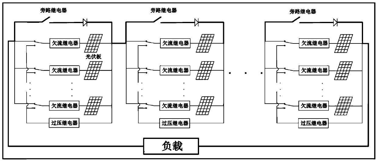
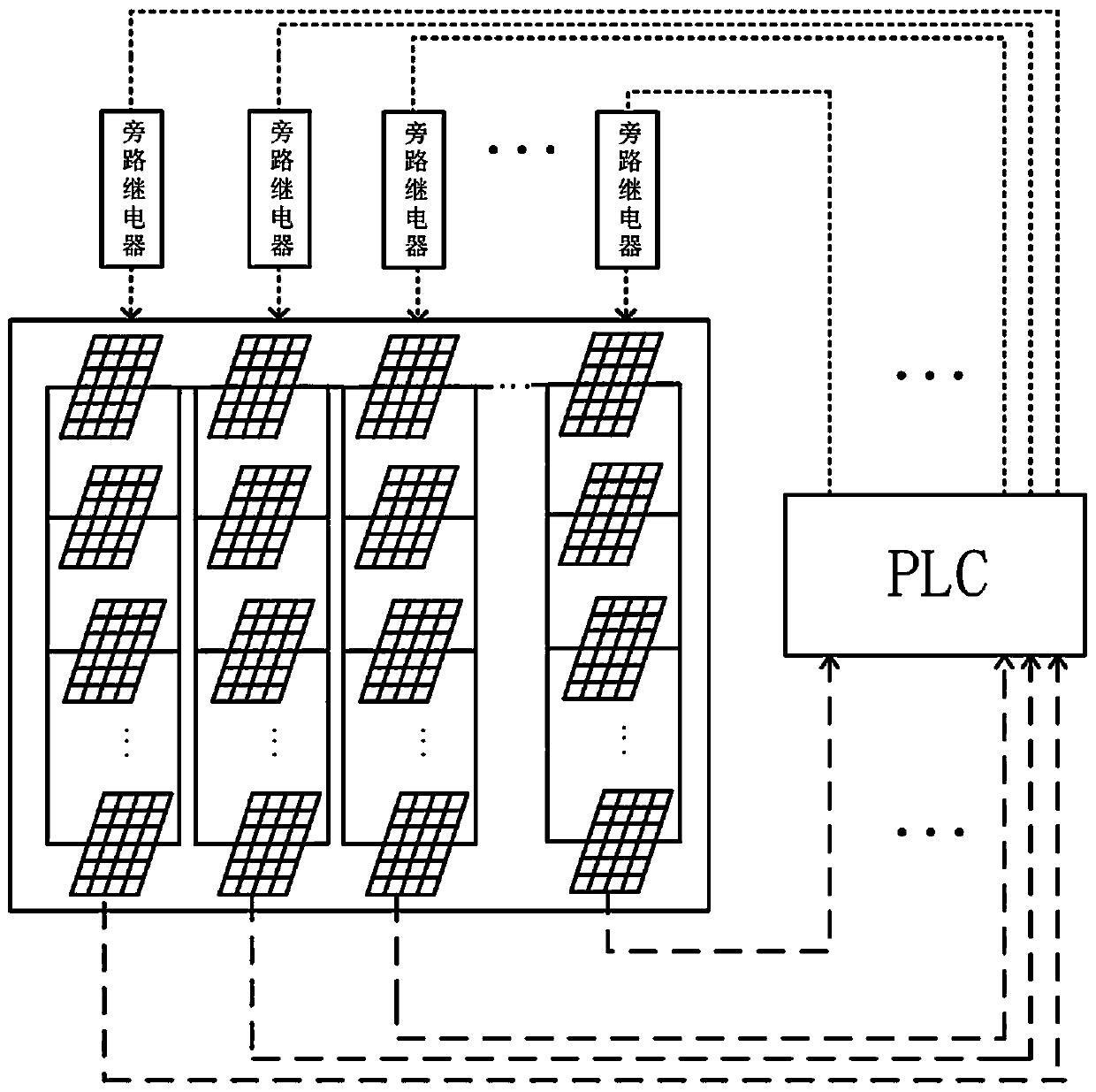
[0061] A photovoltaic array circuit reconfiguration system where the light is partially blocked, such as Figure 1-2 As shown, it includes: photovoltaic array circuit, photovoltaic panel branch switching circuit, bypass circuit driven by reconfiguration logic, electric energy detection and analysis circuit and PLC power optimization module.

[0062] The photovoltaic array circuit is connected in parallel first and then in series to form an m×n photovoltaic array, and the parallel connection of m photovoltaic panels is regarded as a unit group. The photovoltaic panels of each unit group are connected in series with a DC undercurrent relay and a circuit switch, and each unit group is connected in parallel with a voltage limit circuit with an overvoltage relay; when the lig...


PUM


Abstract

The invention discloses a circuit reconstruction system and method for a photovoltaic array where an illumination part is shielded. The system comprises a photovoltaic array circuit, a photovoltaic panel branch switching circuit, a bypass circuit, power detection and analysis circuits, and a PLC power optimization module, wherein the photovoltaic array circuit comprises N rows and M columns of photovoltaic panels; each photovoltaic panel is connected in series with the branch switching circuit; each column of photovoltaic panels is connected in parallel with the bypass circuit; each photovoltaic panel is connected with the power detection and analysis circuit in the corresponding column; and each column of power detection and analysis circuits is connected with the PLC power optimization module. The method includes the following steps of: 1, calculating the power of a reconstruction circuit; and 2, finding out the number of columns to be bypassed when the power reaches a maximum value in order to ensure that the output power of the photovoltaic array is optimal. The photovoltaic array power generation circuit is reconstructed based on the output voltage and a power requirement to improve the efficiency of photovoltaic power generation under non-uniform illumination.

Description

technical field [0001] The invention relates to the technical field of photovoltaic power generation, in particular to a photovoltaic array circuit reconfiguration system and a method thereof in which part of the illumination is blocked. Background technique [0002] With the widespread application of photovoltaic power generation systems, more and more distributed photovoltaic power plants and multi-terrain photovoltaic power plants will face complex and changeable lighting environments. [0003] When the photovoltaic array is partially blocked by trees or buildings, cloudy weather, surface dust or circuit damage, some power generation panels in the photovoltaic array will not be able to generate electricity normally at certain times, which will not only cause the energy loss of photoelectric conversion, but also reduce the overall output power, and will lead to changes in the circuit structure, forming an internal "circulation", which will become a load on the shaded photo...

Claims


Application Information

Patent Timeline
IPC IPC(8): H02S40/30H02S50/00H02J7/35
CPCH02J7/35H02S50/00H02S40/30Y02E10/56
Inventor 郑帅彭云建孙伟杰
Owner SOUTH CHINA UNIV OF TECH
Learn More