Photocatalyst dispersion liquid, photocatalyst composite material and photocatalyst device
A composite material and photocatalyst technology, applied in catalyst activation/preparation, heterogeneous catalyst chemical elements, physical/chemical process catalysts, etc., can solve the problems of insufficient dispersion stability, insufficient coating film activity, etc. High dispersion stability and high acceleration effect
- Summary
- Abstract
- Description
- Claims
- Application Information
AI Technical Summary
Problems solved by technology
Method used
Image

Examples
no. 1 Embodiment approach
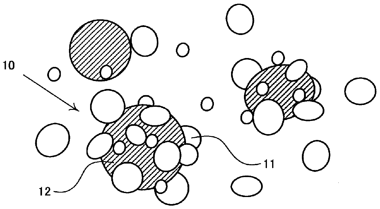
[0026] The catalyst particles contained in the photocatalyst dispersion liquid related to the embodiment are such as figure 1 As shown in , the main catalyst particles and the co-catalyst particles may form mutually composite composite particles 10 in addition to being independently dispersed. This composite catalyst particle 10 includes main catalyst particles 11 and co-catalyst particles 12 . Among them, the average particle diameter of the main catalyst particles is smaller than the average particle diameter of the co-catalyst particles. In addition, in water at 20° C. and pH 6, the zeta potential of the main catalyst particles is negative, and the zeta potential of the co-catalyst particles is positive. Particles with opposite zeta potentials tend to attract each other through electrostatic interactions. At this time, if the main catalyst particles are smaller than the co-catalyst particles, the main catalyst particles tend to surround the co-catalyst particles. As a re...
no. 2 Embodiment approach
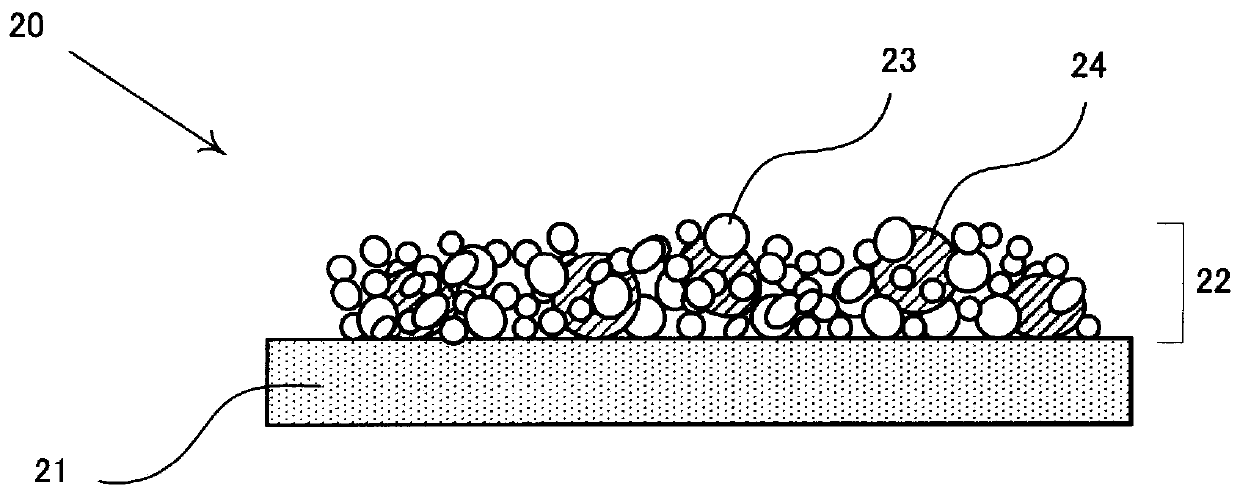
[0041] Such as figure 2 As shown in , the photocatalyst composite material 20 according to the embodiment includes a substrate 21 and a photocatalyst layer 22 . Photocatalyst layer 22 includes main catalyst particles 23 and sub-catalyst particles 24 . Here, the average particle diameter of the main catalyst particles is smaller than the average particle diameter of the cocatalyst particles. In addition, in water at 20° C. and pH 6, the zeta potential of the main catalyst particles is negative, and the zeta potential of the co-catalyst particles is positive. Such a composite material can be obtained by applying the photocatalyst dispersion liquid described in the first embodiment to the surface of a substrate and drying it.
[0042] Particles with opposite zeta potentials become easily attracted to each other electrostatically. As a result, the small main catalyst particles tend to surround and closely adhere to the large co-catalyst particles. Therefore, in the case of ex...
no. 3 Embodiment approach
[0051] Figure 4 A schematic diagram showing an example of the configuration of the photocatalyst device according to the third embodiment is shown in .
[0052] As shown in the figure, the photocatalyst device 40 according to the embodiment includes the photocatalyst composite material 41 according to the second embodiment, a light irradiation member 42 for generating photocatalytic activity on the substrate, and a supply member for supplying substances to the photocatalyst composite material. 43. A chamber 44 including these members may be further provided. In addition, an introduction part 45a for introducing a substance to be processed or a discharge port 45b for discharging a processed substance may be provided.
[0053] Here, the substance to be processed is a substance intended to be changed by a chemical reaction promoted by photocatalysis of the photocatalyst composite material. Specific examples thereof include gases containing toxic components for which removal o...
PUM
| Property | Measurement | Unit |
|---|---|---|
| particle size | aaaaa | aaaaa |
| diameter | aaaaa | aaaaa |
| particle size | aaaaa | aaaaa |
Abstract
Description
Claims
Application Information
 - R&D Engineer
- R&D Manager
- IP Professional
- Industry Leading Data Capabilities
- Powerful AI technology
- Patent DNA Extraction
Browse by: Latest US Patents, China's latest patents, Technical Efficacy Thesaurus, Application Domain, Technology Topic.
© 2024 PatSnap. All rights reserved.Legal|Privacy policy|Modern Slavery Act Transparency Statement|Sitemap