External shell-and-tube heat exchanger and design method thereof
A technology of shell and tube heat exchanger and design method, which is applied in the direction of indirect heat exchanger, heat exchanger shell, heat exchanger type, etc., and can solve the problem of weak high pressure resistance, complicated process, and resistance of seawater to flow through plates Large and other problems, to achieve the effect of reducing resistance loss and reducing the flow field velocity gradient
- Summary
- Abstract
- Description
- Claims
- Application Information
AI Technical Summary
Problems solved by technology
Method used
Image

Examples
Embodiment 1
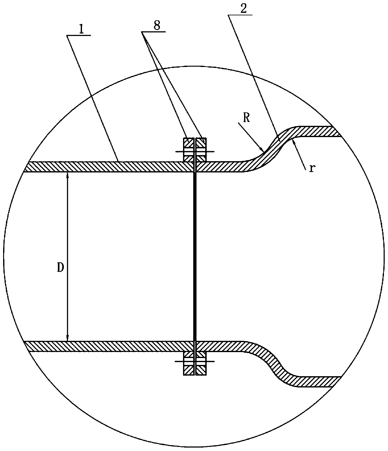
[0034] D = 100mm, α = 0.45, R = 100mm, β = 0.35, assuming that the machining control accuracy is level 7, C = 5, according to the above formula
[0035] r=0.45*100+0.35*100+5=85
Embodiment 2
[0036] Embodiment 2: D = 150mm, α = 0.40, R = 200mm, β = 0.25, assuming that the processing control precision is 8 grades, C = 10, according to the above formula
[0037] r=0.40*150+0.25*200+10=120
[0038] According to the minimum curvature radius r of the variable diameter surface in the water collection chamber obtained above, the design of the shell-and-tube heat exchanger can be realized.
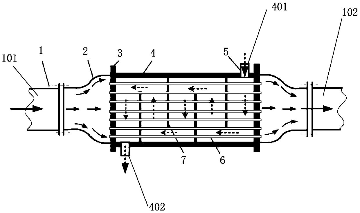
[0039] Such as figure 1 , figure 2 As shown, a shell-and-tube heat exchanger designed by the method of the present invention includes a shell 4 with a fresh water inlet 401 and a fresh water outlet 402, a tube sheet 3, a heat exchange tube 6 and a baffle 7, and the tube sheet 3 They are respectively installed at both ends of the shell 4, and a plurality of baffles 7 arranged at intervals are arranged radially inside the shell 4, and mounting holes are provided on each tube sheet 3 and baffles 7, and a plurality of baffles The heat exchange tubes 6 pass through the mounting holes of...
PUM
 Abstract
Description
Claims
Application Information
 - Generate Ideas
- Intellectual Property
- Life Sciences
- Materials
- Tech Scout
- Unparalleled Data Quality
- Higher Quality Content
- 60% Fewer Hallucinations
Browse by: Latest US Patents, China's latest patents, Technical Efficacy Thesaurus, Application Domain, Technology Topic, Popular Technical Reports.
© 2025 PatSnap. All rights reserved.Legal|Privacy policy|Modern Slavery Act Transparency Statement|Sitemap|About US| Contact US: help@patsnap.com