Resonant Schottky probe device and method of using same

A probe and output terminal technology, applied in the field of resonant Schottky probe devices, can solve the problems of non-adjustable, limited Schottky probe sensitivity, and inability to meet the needs of single proton measurement, and achieve stable performance and easy control operation and debugging installation, the effect of compact structure

Active Publication Date: 2019-09-24
INST OF MODERN PHYSICS CHINESE ACADEMY OF SCI
View PDF5 Cites 6 Cited by
  • Summary
  • Abstract
  • Description
  • Claims
  • Application Information

AI Technical Summary

Problems solved by technology

Loaded Q of the resonant Schottky probe on the three machines above L The values ​​are limited below 1000, therefore, it cannot meet the demand of single proton measurement in the storage ring (requiring load Q L

Method used


Image

  • Resonant Schottky probe device and method of using same
  • Resonant Schottky probe device and method of using same
  • Resonant Schottky probe device and method of using same

Examples


Example Embodiment

[0017] The present invention will be described in detail below in conjunction with the drawings. However, it should be understood that the drawings are only provided for a better understanding of the present invention, and they should not be construed as limiting the present invention. In the description of the present invention, it should be understood that the terms "first", "second", etc. are only used for descriptive purposes, and cannot be understood as indicating or implying relative importance.

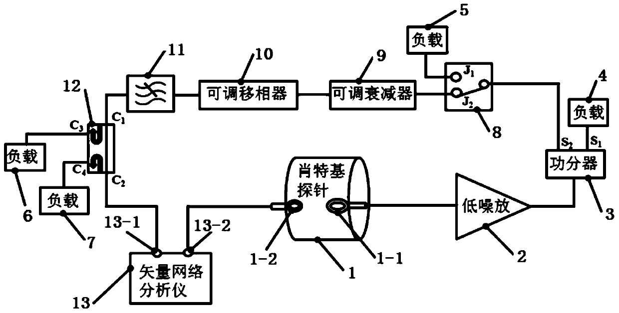
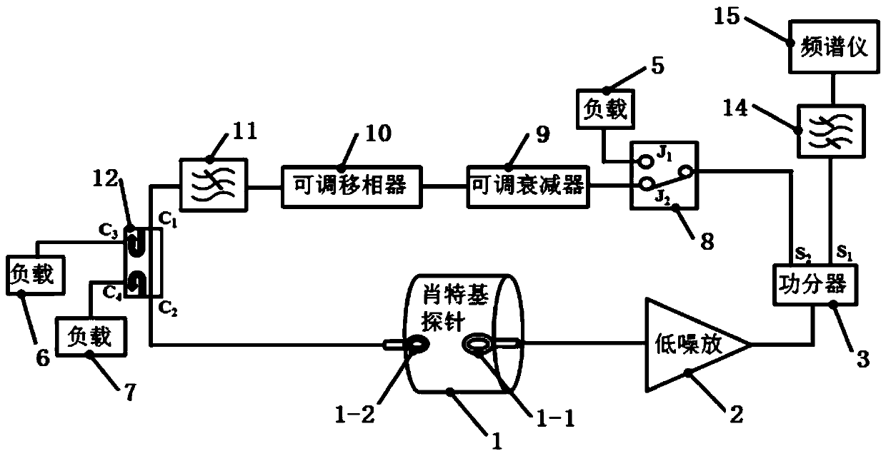
[0018] Such as figure 1 , figure 2 As shown, the resonant Schottky probe device provided by the present invention includes a resonant Schottky probe 1, a low noise amplifier 2, a power divider 3, a first load 4, a second load 5, a third load 6, and a fourth load. Load 7, single-pole double-throw microwave switch 8, adjustable attenuator 9, adjustable phase shifter 10, low-pass filter 11, four-port bidirectional coupler 12, vector network analyzer 13, band-pass filter 14 and spect...


PUM


Abstract

The present invention relates to a resonant Schottky probe device and a method of using the same. The resonant Schottky probe device is characterized by comprising a resonant Schottky probe, wherein the first coupled loop antenna of the resonant Schottky probe is connected to the input end of a power splitter via a low-noise amplifier; the first output end of the power splitter is connected to a first load or a band-pass filter; the band-pass filter is connected to a spectrum analyzer; the second output end of the power splitter is connected to a second load and an adjustable attenuator through a switch; the adjustable attenuator is connected to a low-pass filter through an adjustable phase shifter; the output end of the low-pass filter is connected to the input end of a four-port bidirectional coupler; the coupling end of the four-port bidirectional coupler is connected to a third load and a fourth load; the output end of the four-port bidirectional coupler is connected to the first port of a vector network analyzer or the second coupled loop antenna of the resonant Schottky probe; and the second port of the vector network analyzer is connected to the second coupled loop antenna of the resonant Schottky probe. The resonant Schottky probe device can be widely used in the field of beam diagnosis of heavy ion beam accelerators.

Description

technical field [0001] The invention relates to a resonant Schottky probe device and a using method thereof, and belongs to the field of heavy ion beam (including proton beam) accelerator beam current diagnosis. Background technique [0002] In 1918, the German physicist Walter Schottky first proposed the concept of Schottky noise. In 1972, physicists first observed the proton beam Schottky signal from the ISR machine of the European Nuclear Research Center (CERN). As an important non-intercepting beam diagnosis method, base noise diagnosis is widely used in various accelerator beam measurement systems. The beam current intensity, beam swirl frequency, beam energy, and beam frequency distribution width can be obtained through the Schottky signal. and momentum distribution width and other beam parameters, and the Schottky spectrometer can measure the tune value of the machine, study the stability of the machine, and observe the cooling, accumulation, attenuation and other pro...

Claims


Application Information

Patent Timeline
IPC IPC(8): G01T1/29
CPCG01T1/29
Inventor 朱光宇武军霞张雍谢宏明杜泽景龙魏源顾可伟胡雪静李志学
Owner INST OF MODERN PHYSICS CHINESE ACADEMY OF SCI
Why Eureka
Try Eureka