
Combined phase shifter

A phase shifter and combiner technology, which is applied in circuits, waveguide devices, antennas, etc., can solve problems such as cavity resonance and poor isolation

Inactive Publication Date: 2019-09-24
SOUTH CHINA UNIV OF TECH +1
View PDF5 Cites 6 Cited by
  • Summary
  • Abstract
  • Description
  • Claims
  • Application Information

AI Technical Summary

Problems solved by technology

[0003] Based on this, it is necessary to provide a combined phase shifter for the problems of poor isolation and easy cavity resonance phenomenon in the current combined phase shifter

Method used


Image

  • Combined phase shifter
  • Combined phase shifter
  • Combined phase shifter

Examples


Embodiment Construction

[0024] In order to make the above objects, features and advantages of the present invention more comprehensible, specific implementations of the present invention will be described in detail below in conjunction with the accompanying drawings. In the following description, numerous specific details are set forth in order to provide a thorough understanding of the present invention. However, the present invention can be implemented in many other ways different from those described here, and those skilled in the art can make similar improvements without departing from the connotation of the present invention, so the present invention is not limited by the specific implementations disclosed below.

[0025] Unless otherwise defined, all technical and scientific terms used herein have the same meaning as commonly understood by one of ordinary skill in the technical field of the invention. The terms used herein in the description of the present invention are for the purpose of descr...


PUM


Abstract

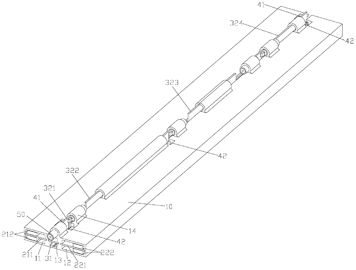
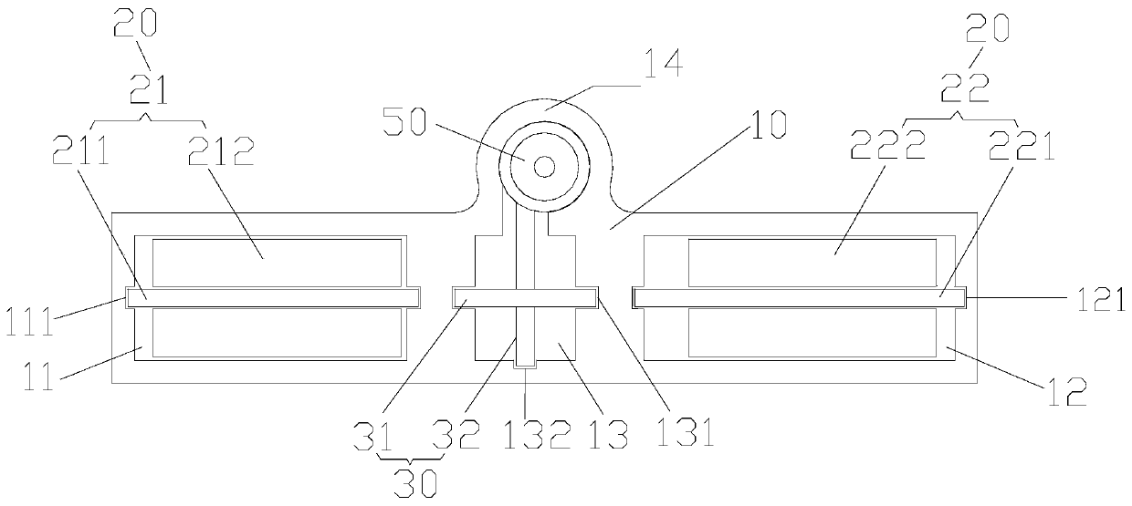
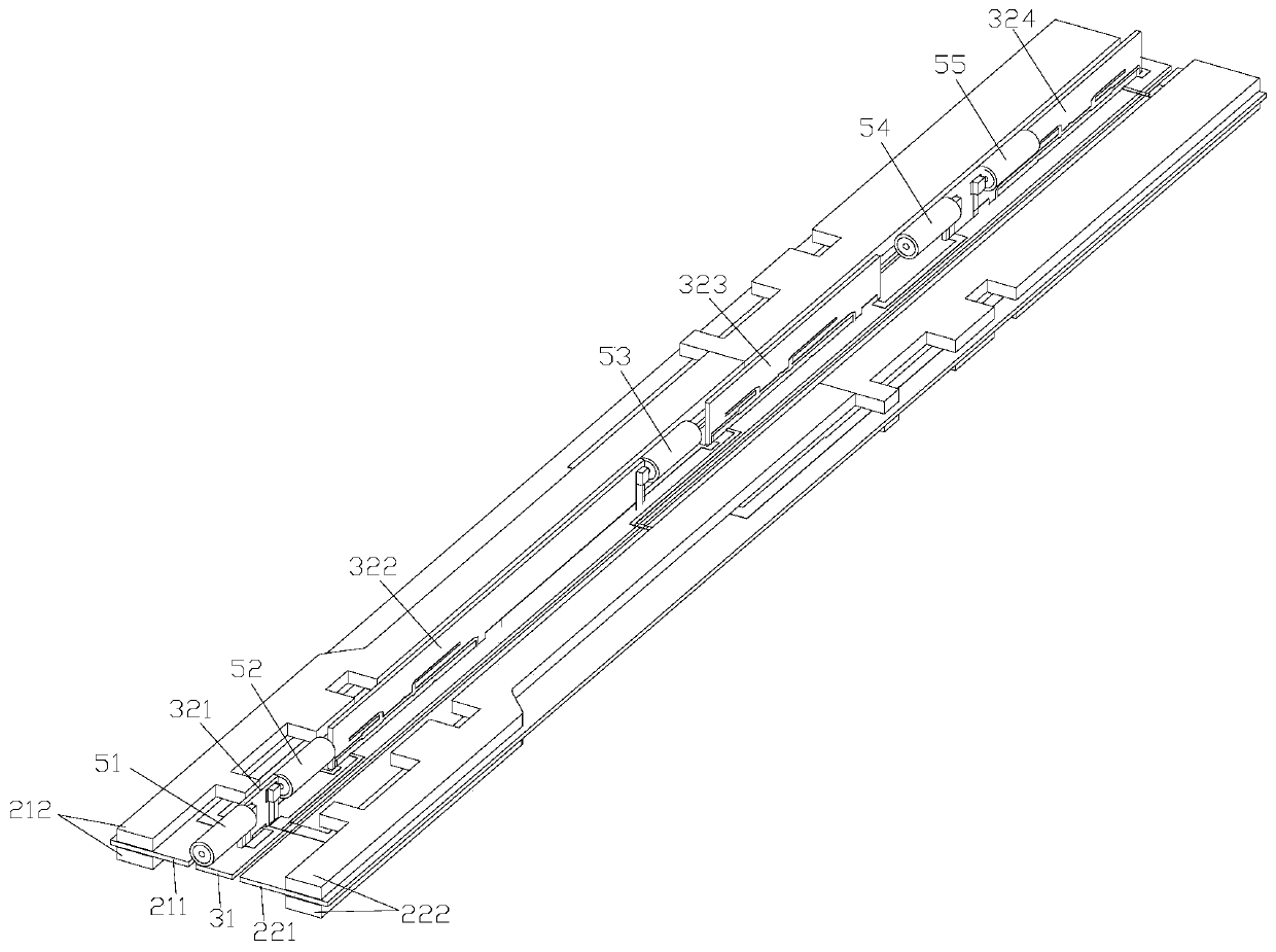
The invention relates to a combined phase shifter comprising a cavity which comprises a first sub-cavity, a second sub-cavity and a third sub-cavity which are arranged separately; a phase shifter module which comprises a first phase shifter and a second phase shifter, wherein the first phase shifter is located in the first sub-cavity, the second phase shifter is located in the second sub-cavity and the first phase shifter and the second phase shifter operate in different frequency bands respectively; and a combiner module which is located in the third sub-chamber and electrically connected with the first phase shifter and the second phase shifter respectively so as to combine and output the frequency band signals outputted from the first phase shifter and the second phase shifter. Therefore, the mutual influence and interference among the modules can be effectively reduced, the isolation among the modules can be greatly improved and the physical size of each sub-cavity is relatively reduced when the overall size of the cavity is unchanged so that the resonance frequency of the cavity can be raised to the working frequency far away from the phase shifter and the resonance phenomena can be effectively avoided.

Description

technical field [0001] The invention relates to the technical field of mobile communication radio frequency devices, in particular to a combined phase shifter. Background technique [0002] With the development of mobile communication technology, multi-frequency antennas play an increasingly important role in network coverage, and in order to facilitate layout and reduce size, it will become a trend to integrate combiners and phase shifters. For example, in the combined phase shifter in the related art, the phase shifter module and the combiner module are integrated in an integrally formed metal cavity. However, due to the limited size of the cavity, the modules are relatively close to each other without any shielding, so there is cross interference between the modules, resulting in strong mutual coupling and poor isolation between the modules, which ultimately leads to poor system performance. In addition, an excessively large cavity structure will cause the phase shifter ...

Claims


Application Information

Patent Timeline
IPC IPC(8): H01P1/18H01Q3/30
CPCH01P1/18H01Q3/30
Inventor 樊凯兵苏国生薛锋章陈礼涛
Owner SOUTH CHINA UNIV OF TECH
Learn More