Robot-controlled pipe joint labeling and packaging device

A technology of packaging equipment and pipe joints, which is applied in the field of machinery, can solve problems such as high labor intensity, high labor cost, and low production efficiency, and achieve the effects of reducing production costs, improving production quality, and improving production efficiency

Pending Publication Date: 2019-09-27
浙江元邦智能装备有限公司
View PDF3 Cites 0 Cited by
  • Summary
  • Abstract
  • Description
  • Claims
  • Application Information

AI Technical Summary

Problems solved by technology

From the above analysis, it can be seen that although the above-mentioned semi-automatic packaging method is better than the completely manual operation method, the above-mentioned manual counting method is time-consuming and laborious, and is prone to counting errors, resulting in inaccurate packaging quantities; at the same time, the manual packaging speed is relatively slow , the labor intensity is high, and the lab

Method used


Image

  • Robot-controlled pipe joint labeling and packaging device
  • Robot-controlled pipe joint labeling and packaging device
  • Robot-controlled pipe joint labeling and packaging device

Examples


Embodiment 1

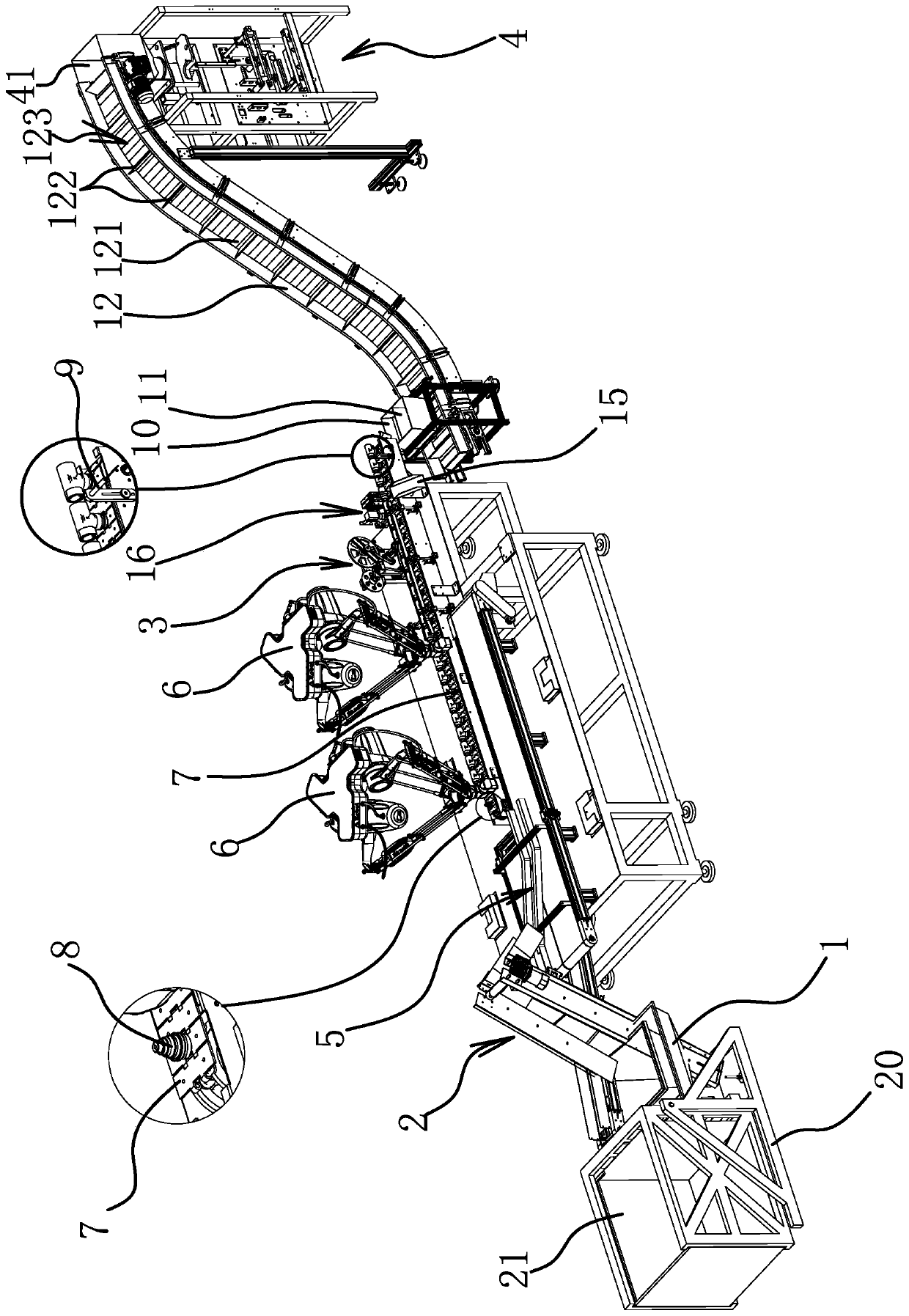
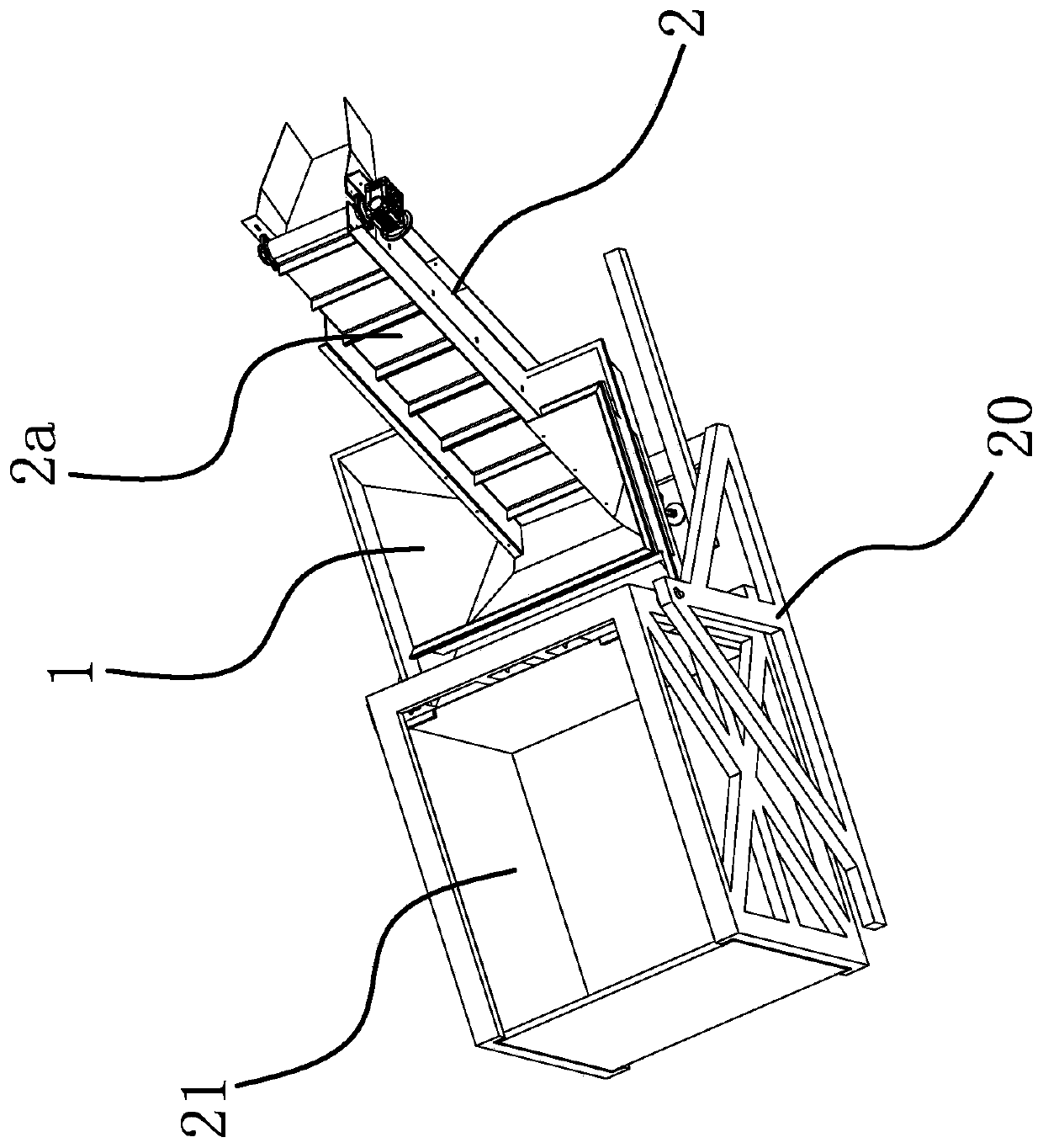
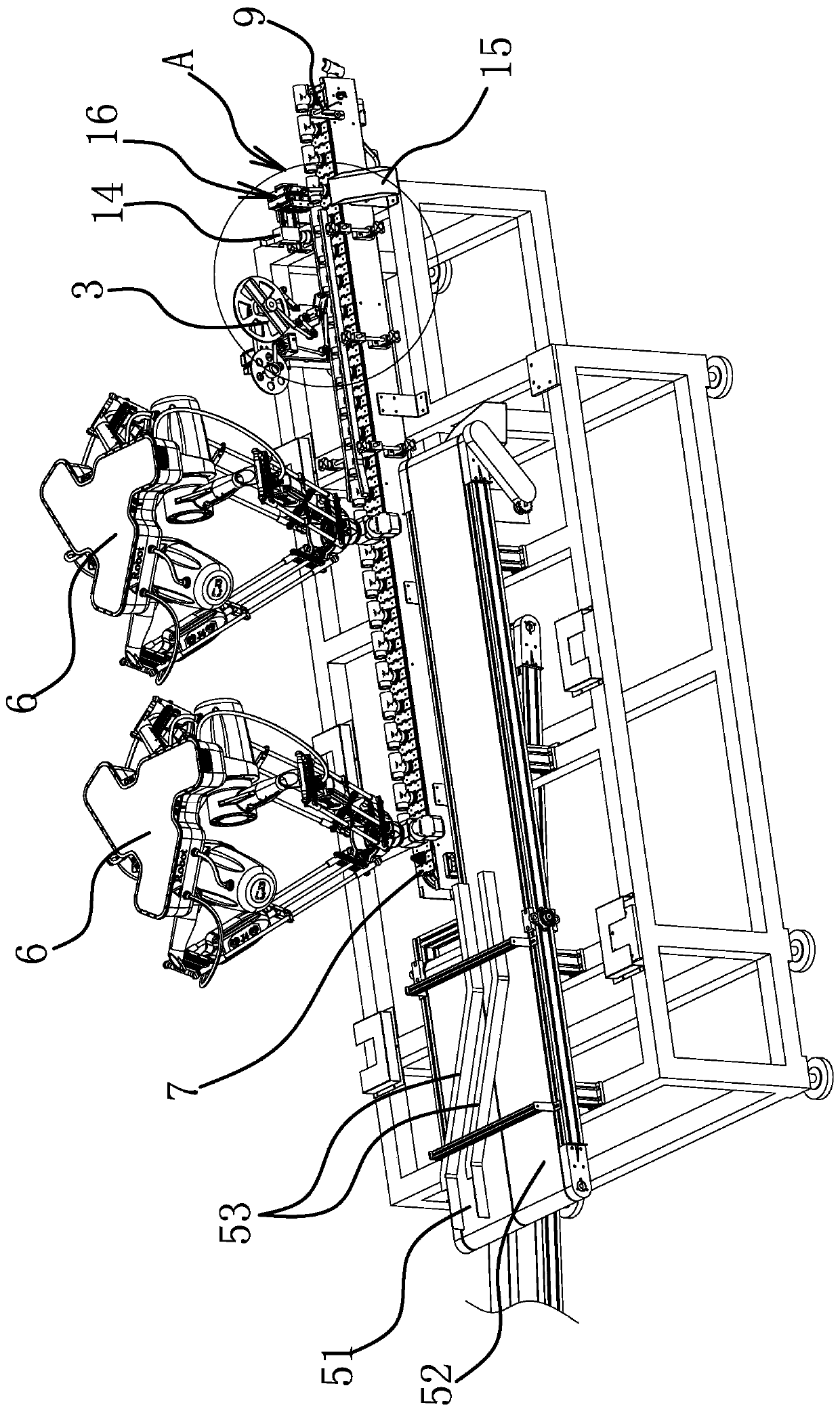
[0027] Specifically, as figure 1 As shown, the pipe joint labeling and packaging equipment controlled by this robot includes a flip feeding device, a silo 1, a feeding machine 2, a labeling machine 3, a bagging and sealing machine for packaging pipe joints 4, a material sorting and conveying mechanism 5, Manipulator 6, labeling conveyor belt 7. Among them, such as figure 2 As shown, the reversing feeding device includes a frame 20 and a feeding box 21 rotatably connected to the frame 20 , and the feeding box 21 can be turned over to the mouth of the silo 1 under the drive of a hydraulic cylinder. The feeder 2 includes a feeding conveyor belt 2a, the input end of the feeding conveyor belt 2a is located at the discharge port of the feed bin 1, the output end of the feeding conveyor belt 2a is connected with the input end of the material handling mechanism 5, and the upper The feeder 2 can transport the pipe joints in the feed bin 1 to the input end of the material handling me...

Embodiment 2

[0033] The technical solution in this embodiment is basically the same as the technical solution in Embodiment 1, the difference is that in this embodiment, the material handling mechanism 5 includes a material handling platform and a material conveyor belt, and the feeding machine 2 can transfer the material The pipe joints in the warehouse 1 are transported to the material handling table. A mechanical gripper capable of grabbing the material onto the material handling conveyor belt is arranged above the material handling platform. The material handling belt is located on one side of the labeling conveyor belt 7.


PUM


Abstract

The invention provides a robot-controlled pipe joint labeling and packaging device, and belongs to the technical field of machines. The robot-controlled pipe joint labeling and packaging device solves the problem about how to improve the production efficiency while ensuring the accuracy of the pipe joint labeling and packaging number. The device comprises a stock bin, a loading machine, a labeling machine, a bagging and sealing machine, a material neatening and conveying mechanism, a manipulator and a labeling conveyor belt; a positioning column is fixedly connected to a belt body of the labeling conveyor belt, a labeling head of the labeling machine is located above the labeling conveyor belt, the manipulator can clamp a pipe joint and arrange the pipe joint on the positioning column in a sleeving manner, and a counting sensor is arranged between the labeling head and the output end of the labeling conveyor belt; and the output end of the labeling conveyor belt is provided with a storage chamber with a through cavity, an impeller is rotatably connected into the through cavity, a quasi-number conveyor is arranged between the storage chamber and the bagging and sealing machine, and the quasi-number conveyor comprises a receiving trough, wherein one receiving trough is located under the storage chamber. The labeling and packaging device realizes full automation of loading, material neatening, labeling, counting and quasi-number packaging.

Description

technical field [0001] The invention belongs to the technical field of machinery and relates to a pipe joint labeling and packaging equipment controlled by a robot. Background technique [0002] Pipes are widely used, the market demand is increasing year by year, and the output of various manufacturers is also increasing year by year. Among them, the pipe joint is a component used to connect water pipes, gas pipes or other pipes. Pipe joints can be divided into external thread end connection type pipe joints, ferrule type pipe joints, self-fixing type pipe joints, etc. according to the use method. According to actual production needs, some mass-produced pipe joints need to be counted, labeled, and packaged before storage or transportation, that is, according to market sales needs, the pipe joints are labeled and then packaged according to the required quantity. [0003] At present, the labeling and packaging of pipe joints in the existing market generally adopts a semi-aut...

Claims


Application Information

Patent Timeline
IPC IPC(8): B65B65/00B65B19/34B65B61/02B65B65/08B65C3/02B65C9/02B65C9/06
CPCB65B19/34B65B61/02B65B65/003B65B65/08B65C3/02B65C9/02B65C9/06
Inventor 金龙梅海波金依能徐建华颜灵江敬江
Owner 浙江元邦智能装备有限公司
Why Eureka
Try Eureka