A turbine draft tube with circular and elliptical grids

A technology of elliptical and hydraulic turbines, applied in mechanical equipment, hydroelectric power generation, engine components, etc., can solve problems such as shedding, achieve the effect of suppressing backflow phenomenon, reducing obvious, and reducing vortex energy

Active Publication Date: 2020-11-03
JIANGSU UNIV
View PDF8 Cites 0 Cited by
  • Summary
  • Abstract
  • Description
  • Claims
  • Application Information

AI Technical Summary

Problems solved by technology

[0005] The purpose of the present invention is to solve the problem of de-flow and secondary backflow caused by the water flowing through the draft tube during the operation of the existing water turbine, and to propose a circular water turbine with the ability to reduce radial pressure fluctuations and improve smooth operation. and elliptical mesh turbine draft tube

Method used


Image

  • A turbine draft tube with circular and elliptical grids
  • A turbine draft tube with circular and elliptical grids
  • A turbine draft tube with circular and elliptical grids

Examples


Embodiment Construction

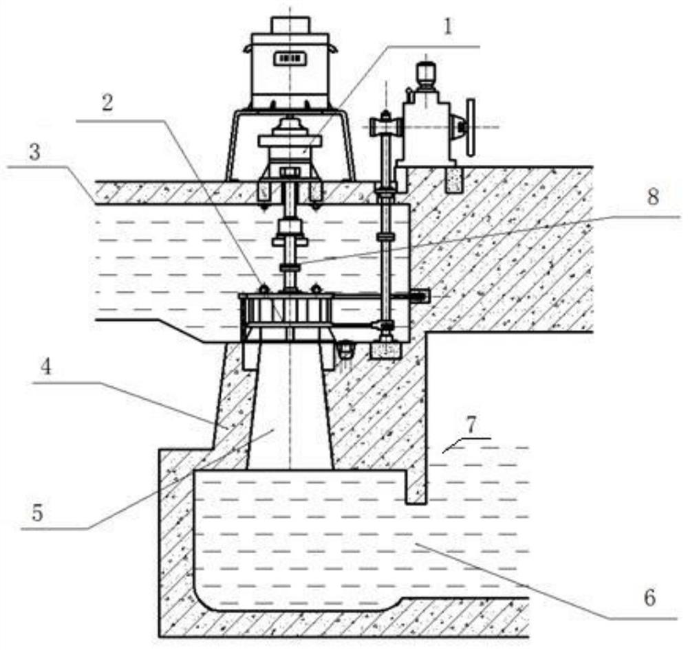
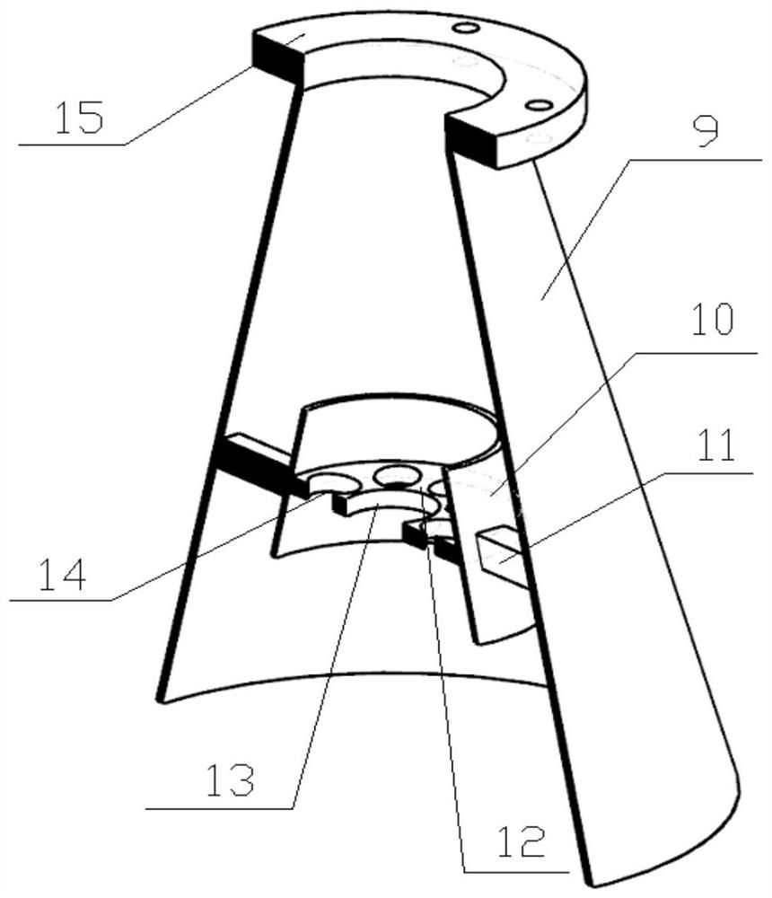
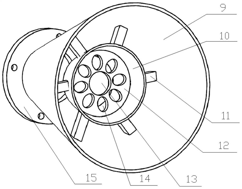
[0019] see figure 2 and image 3 , The draft tube 5 of the present invention is composed of a straight cone 9 , a splitter 10 , a splitter 12 and a support frame 11 . The outermost is a straight cone 9, the axial section of the straight cone 9 is conical, the upper end of the straight cone 9 is a water inlet, which is a small conical end, and the lower end is a water outlet, which is a large conical end. 9. The inside is connected from the water inlet to the water outlet. A flange 15 is installed at the upper end of the straight cone 9, and the straight cone 9 is fixed by the flange 15.

[0020] A splitter tube 10 is arranged inside the straight cone tube 9 , the axial section of the splitter tube 10 is also conical, and the central axis of the splitter tube 10 is collinear with the central axis of the straight cone tube 9 . The upper end of the splitter cylinder 10 is a small tapered end, and the lower end is a large tapered end. Splitter cylinder 10 is empty sleeved ins...


PUM


Abstract

The invention discloses a water turbine draft tube with circular and oval grids in the technical field of vane type fluid machinery. The outermost part is a straight cone cylinder with a conical axial section, and a shunting cylinder is arranged in the straight cone cylinder; a supporting frame is fixedly connected between the outer side wall of the shunting cylinder and the inner side wall of the straight cone cylinder, and a disc-shaped shunting piece is arranged in the shunting cylinder; the outer wall of the shunting piece and the inner wall of the shunting cylinder are sealed and fixedly connected, a through round hole is formed in the middle of the shunting piece, a plurality of identical elliptical holes are uniformly formed in the shunting piece on the outer side of the round hole in the circumferential direction, and the long axis direction of each elliptical hole is along the diameter direction of the shunting piece; the shunting piece is used for crushing a vortex strip and reducing the pressure pulsation caused by the vortex strip; and due to the fact that the grids on the shunting piece are oval and circular, fluid separation and disengagement are small, the pressure difference between the interior periphery and the center of the draft tube is reduced, the radial pulsation of the vortex strip is weakened, the cavitation caused by the vortex strip in the draft tube is reduced, and the service life of the draft tube is prolonged.

Description

technical field [0001] The invention belongs to the technical field of vane type fluid machinery, and relates to a draft tube structure of a Francis water turbine. Background technique [0002] The water turbine is a kind of turbo machinery, as a blade type fluid machine, it is installed in such as figure 1 In the hydropower station shown, the water turbine converts the potential energy of water into kinetic energy through the potential difference of water level to drive power generation. like figure 1 As shown, the water turbine 2 is installed in the upstream water level 3 of the dam body 4 , and the rotating main shaft 8 of the water turbine 2 connects with the main shaft of the generator 1 and connects with the runner of the water turbine 2 at the same time. A draft tube 5 is placed directly below the outlet of the runner of the water turbine 2, and the draft tube 5 is embedded in the dam body 4, and the downstream water level 7 is located below the draft tube 5. The r...

Claims


Application Information

Patent Timeline
Patent Type & Authority Patents(China)
IPC IPC(8): F03B3/18F03B11/04
CPCF03B3/18F03B11/04Y02E10/20
Inventor 张聪何秀华杨千
Owner JIANGSU UNIV
Why Eureka
Try Eureka