

A system and method for monitoring vibration phase of rcp main pump in nuclear power plant
A vibration phase and monitoring system technology, applied in the field of measurement, can solve the problems of inability to monitor the phase online, lack of online analysis and diagnosis basis, etc., to reduce the number of starts and stops and the time of the dynamic balancing window, reduce the occupation of critical paths for downtime and overhaul, and reduce radiation. effect of dose
- Summary
- Abstract
- Description
- Claims
- Application Information
AI Technical Summary
Problems solved by technology
Method used
Image

Examples
Embodiment 1
[0043] A nuclear power plant RCP main pump vibration phase monitoring system, such as image 3 As shown, the system includes:
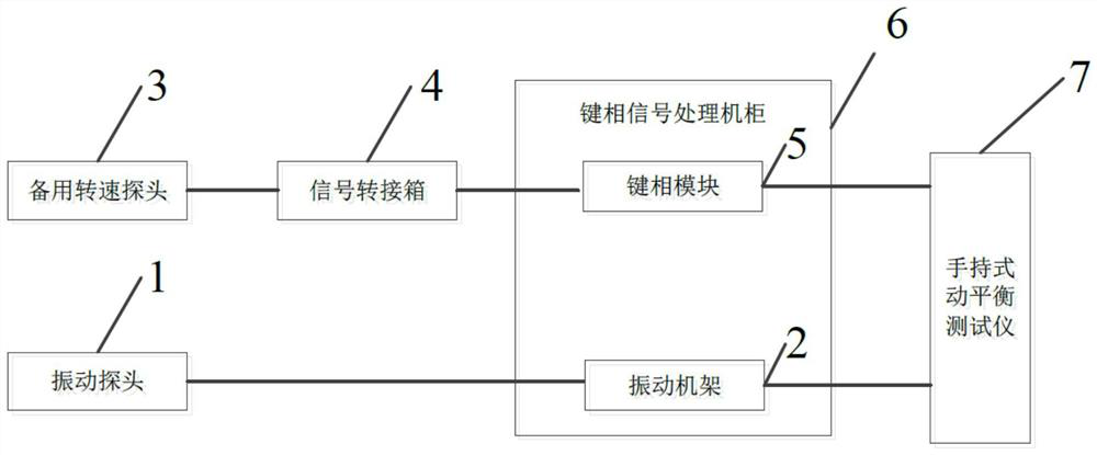
[0044] Vibration probe 1: electrically connected to the vibration frame, used to collect vibration signals on the measured shaft;
[0045] Vibration rack 2: electrically connected to the hand-held dynamic balance tester, used to process the vibration signal collected by the vibration probe;
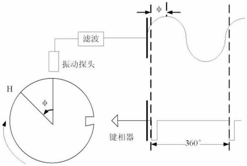
[0046] Standby rotational speed probe 3: be electrically connected with signal transition box, be used for collecting pulse signal, described pulse signal is the pulse signal that produces when the measured shaft rotates every revolution;
[0047] Signal transfer box 4: electrically connected to the spare speed probe and the key phase module in the key phase signal processing cabinet, used to shunt the pulse signals collected by the spare speed probe and transmit them to the speed signal processing unit and the key phase signal processing cabinet respectively T...
Embodiment 2
[0053] A nuclear power plant RCP main pump vibration phase monitoring system, such as figure 1 As shown, the system includes:
[0054] Vibration probe 1: electrically connected to the vibration frame, used to collect vibration signals on the measured shaft;
[0055] Vibration rack 2: electrically connected to the hand-held dynamic balance tester, used to process the vibration signal collected by the vibration probe;
[0056]Standby rotational speed probe 3: be electrically connected with signal transition box, be used for collecting pulse signal, described pulse signal is the pulse signal that produces when the measured shaft rotates every revolution;
[0057] Signal transfer box 4: electrically connected with the spare speed probe, the key phase signal processing cabinet, and the speed signal processing unit, used to shunt the pulse signals collected by the spare speed probe, and transmit them to the speed signal processing unit and the key phase signal processing cabinet re...
Embodiment 3
[0063] A nuclear power plant RCP main pump vibration phase monitoring system, such as image 3 As shown, the system includes:
[0064] Vibration probe 1: electrically connected to the vibration frame, used to collect vibration signals on the measured shaft;
[0065] Vibration rack 2: electrically connected to the hand-held dynamic balance tester, used to process the vibration signal collected by the vibration probe;
[0066] Standby rotational speed probe 3: be electrically connected with signal transition box, be used for collecting pulse signal, described pulse signal is the pulse signal that produces when the measured shaft rotates every revolution;
[0067] Signal transfer box 4: electrically connected to the spare speed probe, the speed signal processing unit and the key phase module in the key phase signal processing cabinet, used to shunt the pulse signals collected by the spare speed probe and transmit them to the speed signal processing unit and The key phase module...
PUM
 Abstract
Description
Claims
Application Information