Gas-liquid separation and cooling system

A cooling system, gas-liquid separation technology, applied in liquid fuel engines, pump components, components of pumping devices for elastic fluids, etc., can solve the problem of not very ideal cooling effect, etc. The effect of sufficient time to eliminate potential hazards

Pending Publication Date: 2019-09-27
WEIGULE VACUUM EQUIP (ZHEJIANG) CO LTD
View PDF3 Cites 2 Cited by
  • Summary
  • Abstract
  • Description
  • Claims
  • Application Information

AI Technical Summary

Problems solved by technology

[0005] Although the above-mentioned patent realizes the cooling of the working fluid and the gas sealing, the cooling effect of the jacket water cooling or coil water cooling is not very ideal.

Method used


Image

  • Gas-liquid separation and cooling system
  • Gas-liquid separation and cooling system
  • Gas-liquid separation and cooling system

Examples


Embodiment 1

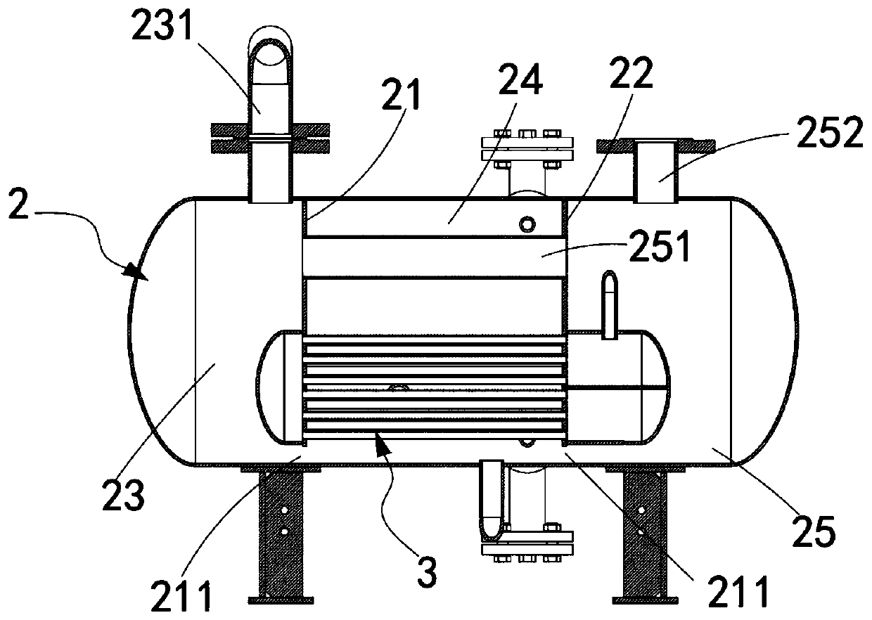
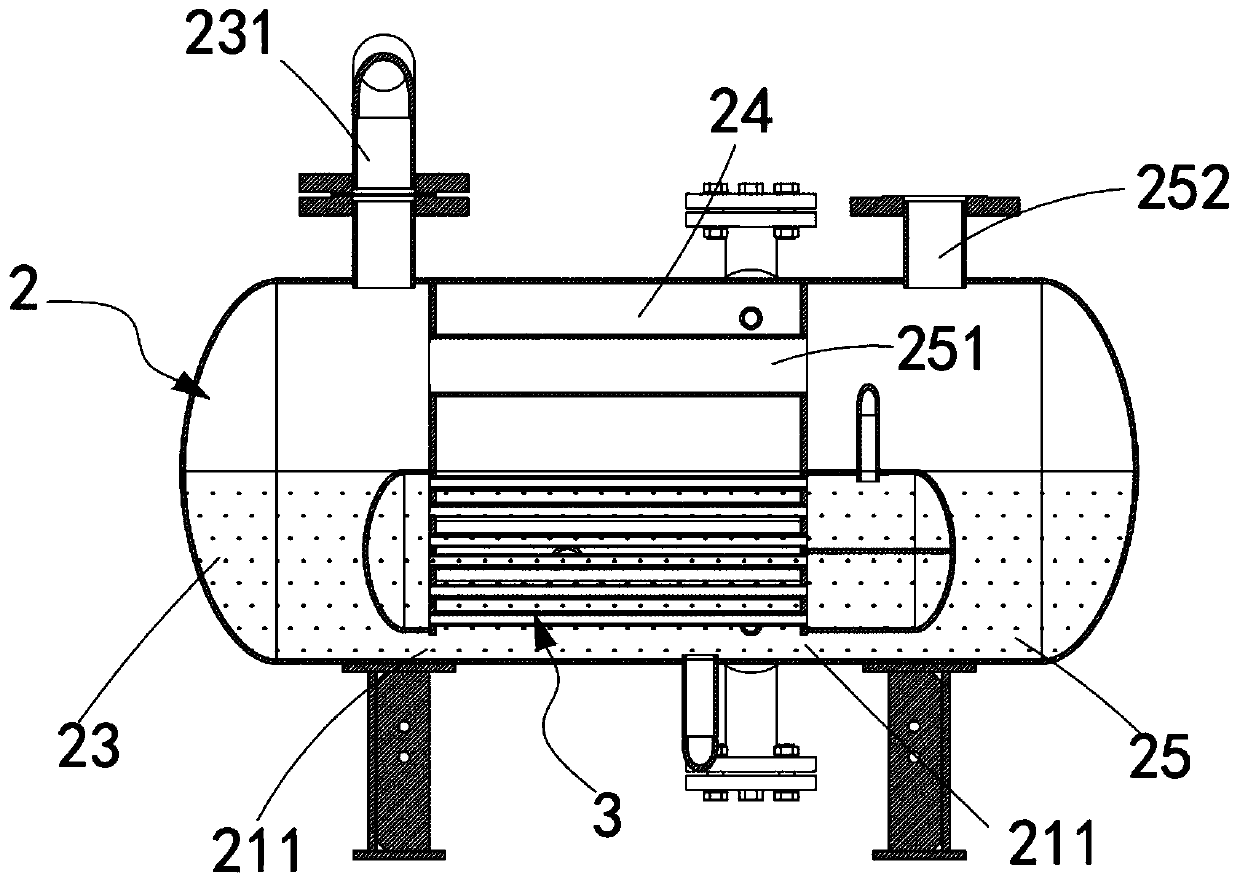
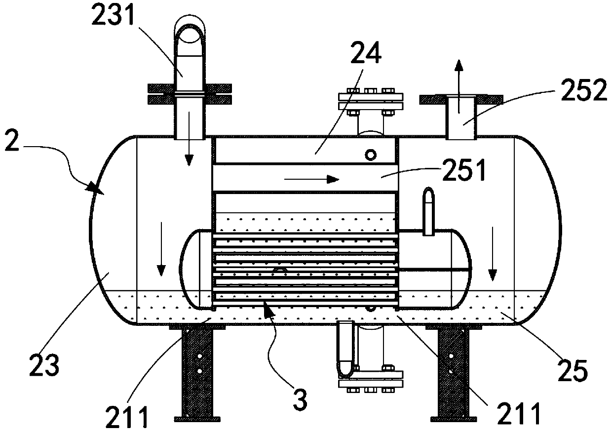
[0047] like figure 1 , Figure 7 to Figure 10 As shown, a gas-liquid separation cooling system includes:

[0048] Gas-liquid separation tank 2, the gas-liquid separation tank 2 is arranged horizontally, and along its horizontal direction, the gas-liquid separation tank 2 is provided with a first liquid level separator 21 and a second liquid level separator 22 to make the gas-liquid separation tank 2 The separation tank 2 is sequentially divided into a first tank compartment 23, a second tank compartment 24 and a third tank compartment 25; and

[0049] a cooler 3, the cooler 3 is arranged inside the gas-liquid separation tank 2 and spans the first tank compartment 23, the second tank compartment 24 and the third tank compartment 25, and It cools the working fluid in the gas-liquid separation tank 2;

[0050] Wherein, the bottoms of the first liquid level separator 21 and the second liquid level separator 22 are both provided with a flow port 211 , through which the first tan...


PUM


Abstract

The invention provides a gas-liquid separation and cooling system. A gas-liquid separation tank of the system is divided into a first tank body partition cavity, a second tank body partition cavity and a third tank body partition cavity through liquid level partition plates, wherein the first tank body partition cavity, the second tank body partition cavity and the third tank body partition cavity communicate through bottoms, a cooling pipe is arranged in the second tank body partition cavity, when a pump body is started initially, the pressure generated by the pump body enables working liquid in the first tank body partition cavity and working liquid of the third tank body partition cavity to be concentrated into the second tank body partition cavity, rapid heat exchange cooling is carried out through cooling liquid flowing in the cooling pipe, so that the technical problem of rapid cooling of working liquid of the pump body is solved, meanwhile, the sealing of gas is realized, so that no leakage of the gas is ensured.

Description

technical field [0001] The invention relates to the technical field of gas-liquid separation and cooling liquid cooling equipment, in particular to a gas-liquid separation cooling system. Background technique [0002] In the occasions where the gas and liquid phases are separated and the liquid phases are cooled, such as steam recovery, exhaust gas treatment and other working environments, especially in the returning working environment where flammable, explosive, toxic and other gases are extracted, the gas must be sent to the designated pipe. It is absolutely not allowed to leak and discharge into other pipelines. If it is leaked or discharged into other pipelines, it will cause economic losses in light, and endanger the safety of life and property and cause safety accidents in serious cases. In addition, due to the need to be in this working environment and to realize the characteristics of isothermal compression of the pump body that extracts the gas, the working fluid ...

Claims


Application Information

Patent Timeline
Patent Type & Authority Applications(China)
IPC IPC(8): F04C19/00F04C29/04
CPCF04C19/004
Inventor 唐兴鹏汤浜浜
Owner WEIGULE VACUUM EQUIP (ZHEJIANG) CO LTD
Why Eureka
Try Eureka