Metal radiation ceiling board and preparation method thereof

A radiant ceiling and metal technology, applied to the ceiling, heating methods, lighting and heating equipment, etc., can solve the problem of wasting the heat exchange effect of the heat exchange surface of the coil, the poor heat exchange effect of the heat exchange tube, and the unsatisfactory heat exchange effect of the ceiling and other problems, to achieve the effects of easy processing and implementation, reducing poor heat transfer effect, and enhancing energy storage and heat conduction capabilities

Inactive Publication Date: 2019-09-27
SHANGHAI UNIV OF ENG SCI
View PDF6 Cites 3 Cited by
  • Summary
  • Abstract
  • Description
  • Claims
  • Application Information

AI Technical Summary

Problems solved by technology

However, in the existing radiant ceiling products, there is a problem that the fins have a small wrapping surface for the coil, which wastes part of the heat exchange effect of the heat exchange surface of the coil, resulting in the unsatisfactory heat exchange effect of the entire ceiling.
[0003] Chinese patent CN203964148U discloses a radiant air-conditioning terminal combined with a metal ceiling board, which mainly includes a metal ceiling board, copper pipes, aluminum base, aluminum foil and insulation materials; the copper pipe is wrapped by an aluminum base and a metal ceiling board, Aluminum foil and insulation material are arranged above the aluminum base; the metal ceiling board can be a perforated board or a non-perforated board; in this patent, the copper pipe is wrapped by the aluminum base and the metal ceiling board to prevent the copper pipe from falling off, but the copper pipe There is a contact connection with the metal base, and the metal base and the copper tube are only in contact with the upper part, and the contact area is small, resulting in poor heat exchange effect of the heat exchange tube

Method used


Image

  • Metal radiation ceiling board and preparation method thereof
  • Metal radiation ceiling board and preparation method thereof
  • Metal radiation ceiling board and preparation method thereof

Examples


Embodiment 1

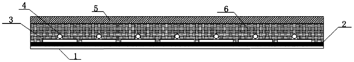
[0035] A metal radiant ceiling panel such as figure 1 As shown, it includes metal gusset 1, sound insulation cotton 2, radiation unit, phase change energy storage material 6 and insulation layer 5 arranged in sequence from bottom to top; the bottom of the radiation unit is placed on the sound insulation cotton 2, and the radiation unit is Variable energy storage material 6 is tightly packed.

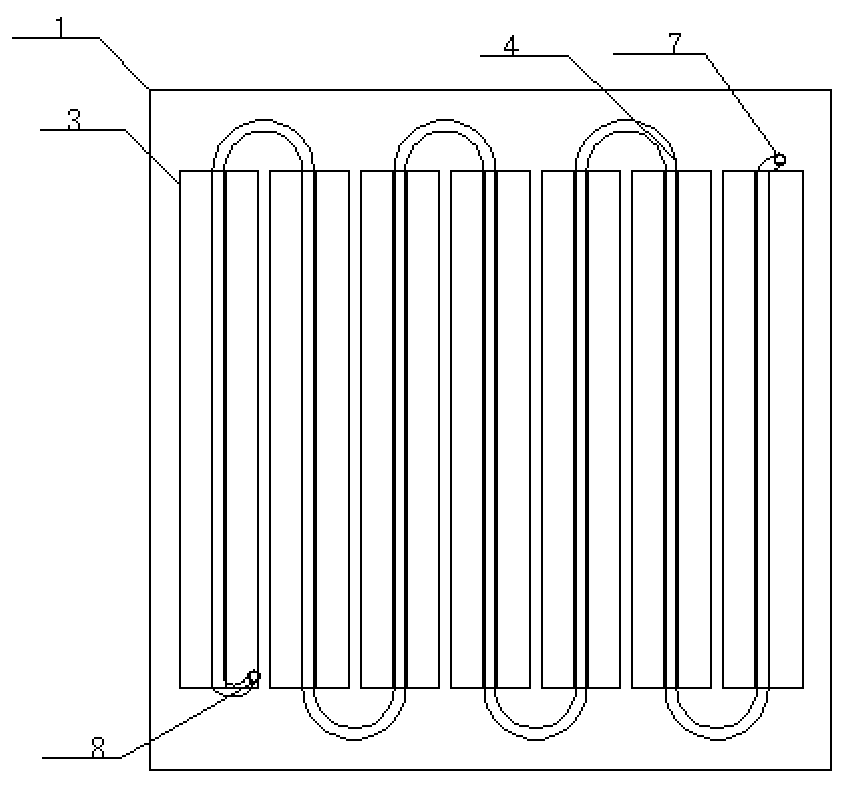
[0036] Among them, such as figure 2 As shown, the radiating unit includes several fins 3 arranged side by side, and there is a gap between two adjacent fins 3; each fin 3 has a through hole 9 along its length, and the fins 3 and the through-holes 9 inside the fins 3 are all arranged in parallel; the through-holes 9 inside the fins 3 are sequentially connected through the connecting pipe 4 to form an S-shaped pipeline, which is a channel for the flow of heat exchange fluid, wherein the through-holes 9 The inner diameter is equal to the inner diameter of the connecting pipe 4; in this e...

Embodiment 2

[0047] A metal radiant ceiling panel such as figure 1 As shown, it includes metal gusset 1, sound insulation cotton 2, radiation unit, phase change energy storage material 6 and insulation layer 5 arranged in sequence from bottom to top; the bottom of the radiation unit is placed on the sound insulation cotton 2, and the radiation unit is Variable energy storage material 6 is tightly packed.

[0048] Among them, such as figure 2As shown, the radiating unit includes several fins 3 arranged side by side, and there is a gap between two adjacent fins 3; each fin 3 has a through hole 9 along its length, and the fins 3 and the through-holes 9 inside the fins 3 are all arranged in parallel; the through-holes 9 inside the fins 3 are sequentially connected through the connecting pipe 4 to form an S-shaped pipe, which is a passage for the heat exchange fluid to circulate, and the inner diameter of the through-hole 9 is The size is equal to the inner diameter of the connecting pipe 4;...

Embodiment 3

[0058] A metal radiant ceiling panel such as figure 1 As shown, it includes metal gusset 1, sound insulation cotton 2, radiation unit, phase change energy storage material 6 and insulation layer 5 arranged in sequence from bottom to top; the bottom of the radiation unit is placed on the sound insulation cotton 2, and the radiation unit is Variable energy storage material 6 is tightly packed.

[0059] Among them, such as figure 2 As shown, the radiation unit includes several fins 3 arranged side by side, and there is a gap between two adjacent fins 3; each fin 3 is provided with a straight tube along its length, and the fins 3 and The through-straight tubes inside the fins 3 are all arranged in parallel; the through-straight tubes inside the fins 3 are sequentially connected through the connecting pipe 4 to form an S-shaped pipeline, which is a channel for the circulation of heat exchange fluid, and the inner diameter of the through-straight tubes is the same as The inner di...


PUM


Abstract

The invention relates to a metal radiation ceiling board. The metal radiation ceiling board comprises a metal pinch plate, sound insulation cotton, a radiating unit, a phase change energy storage material and a heat insulation layer. The radiating unit comprises a plurality of fins arranged in parallel. Each fin is internally provided with a penetration straight pipe in the length direction of the fin. The penetration straight pipes in the fins communicate through connecting pipes in sequence to form a channel allowing heat exchange fluid to circulate. Compared with the prior art, the connecting pipes in the metal radiation ceiling board are directly processed in the fins; each connecting pipe and the corresponding fin are of an integrated structure; contact thermal resistance caused by a traditional external coil is avoided, and the heat exchange effect is improved; and the metal radiation ceiling board has the advantages of high heat exchange efficiency and energy utilization rate, good in heat retaining capacity, low noise and the like.

Description

technical field [0001] The invention relates to the field of metal radiant ceilings, in particular to a metal radiant ceiling board and a preparation method thereof. Background technique [0002] Ceiling radiant cooling / heating is a form of air conditioning system, and its heat exchange tubes are installed above the ceiling, making the ceiling the main component of the air conditioning system. Compared with the traditional air-conditioning system, the metal radiant ceiling system has considerable comfort and environmental health, the largest degree of architectural freedom, good heat transfer effect, high heat transfer efficiency per unit area, and a higher energy efficiency throughout the life of the building. features such as energy efficiency. Radiant ceilings have been widely used in some public large buildings. However, in the existing radiant ceiling products, there is a problem that the wrapping surface of the fins on the coil is small, which wastes part of the heat...

Claims


Application Information

Patent Timeline
Patent Type & Authority Applications(China)
IPC IPC(8): F24F5/00F24D15/02E04B9/00
CPCE04B9/001F24D15/02F24D2220/10F24F5/0092
Inventor 曹振傅允准
Owner SHANGHAI UNIV OF ENG SCI
Why Eureka
Try Eureka