Railway vehicle line collision test method

A line collision and test method technology, applied in the field of rail vehicle line collision test, can solve the problems of poor test safety and stability, and achieve the effects of improving system redundancy, reducing losses, and improving work reliability

Active Publication Date: 2019-09-27
ZHUZHOU TIMES ELECTRONICS TECH CO LTD +1
View PDF13 Cites 6 Cited by
  • Summary
  • Abstract
  • Description
  • Claims
  • Application Information

AI Technical Summary

Problems solved by technology

[0010] In view of this, the purpose of the present invention is to provide a rail vehicle line collision test method, to solve the existing line collision test method must complete a series of rail train collision test control process such as dynamic decoupling on the test vehicle, can not realize the experimental process Remote control, technical problems of poor test safety and stability

Method used


Image

  • Railway vehicle line collision test method
  • Railway vehicle line collision test method
  • Railway vehicle line collision test method

Examples


Embodiment 1

[0063] as attached Figure 7 And attached Figure 8 Shown, a kind of embodiment of rail vehicle circuit crash test method of the present invention, specifically comprises the following steps:

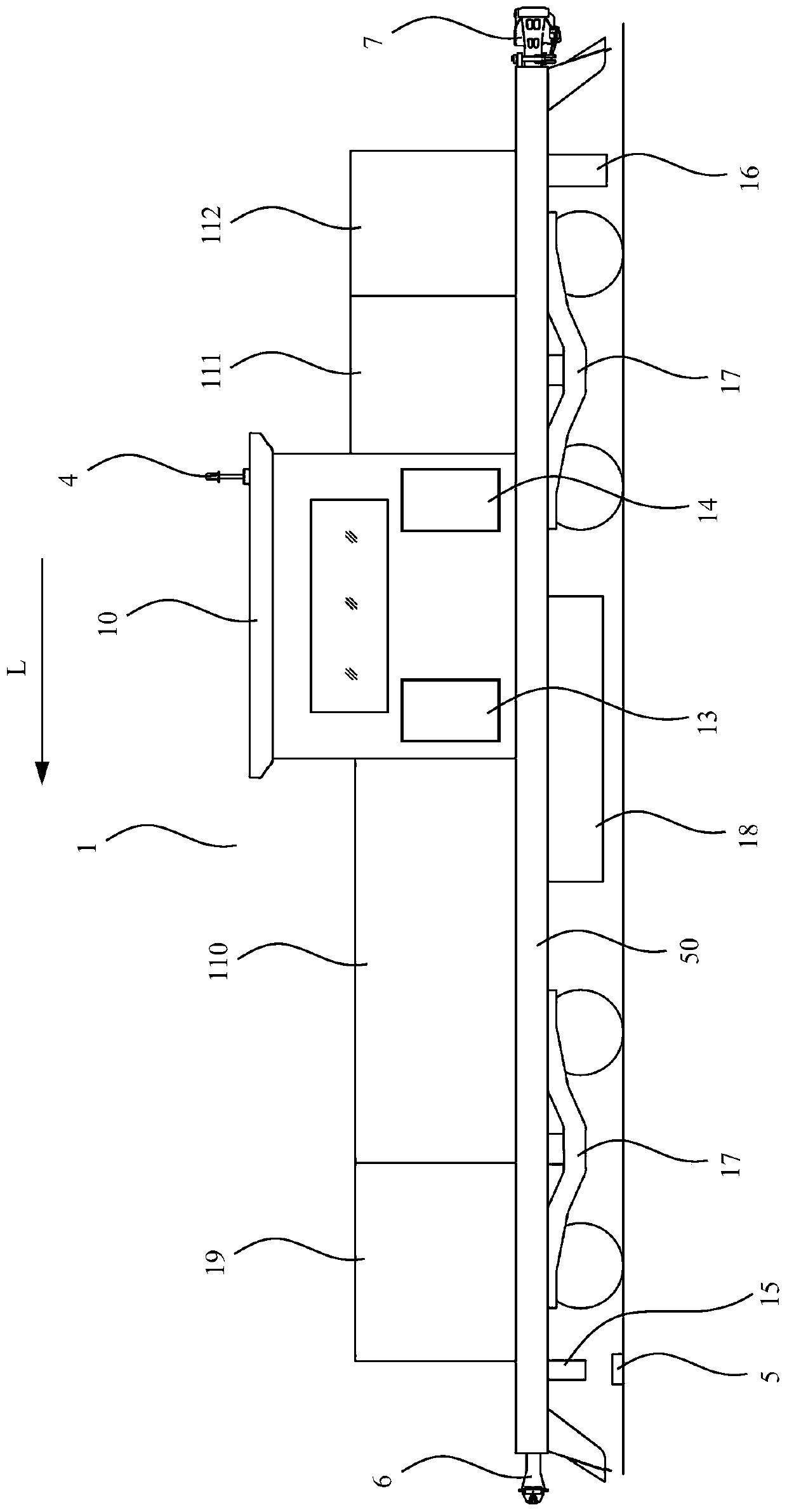
[0064]A) When the vehicle under test 30 starts to carry out the collision test on the track 8 along the direction shown in L, the test drive vehicle 1 is connected with the vehicle under test 30 by the first coupler 6, and the test drive vehicle 1 promotes the vehicle under test 30 to start and Accelerated operation, as attached Figure 7 The stage shown in A;

[0065] B) When the operating speed of the test driving vehicle 1 and the tested vehicle 30 reaches the specified speed of the test, the test driving vehicle 1 and the tested vehicle 30 keep running at a constant speed for a period of time, as shown in the attached Figure 7 The stage shown in B;

[0066] C) When the tested vehicle 30 arrives at the decoupling point position corresponding to the ground beacon 5 (attached Fi...

Embodiment 2

[0078] as attached Figure 5 Shown, a kind of embodiment based on the rail vehicle circuit crash test method of the method described in embodiment 1, specifically comprises the following steps:

[0079] A) The test driving vehicle 1 is connected to the tested vehicle 30 through the first coupler 6. The first coupler 6 adopts a close-connected coupler with an automatic decoupling function, and the test driving vehicle 1 is used as a rail tractor to pull the tested vehicle 30. attached Figure 8 shown;

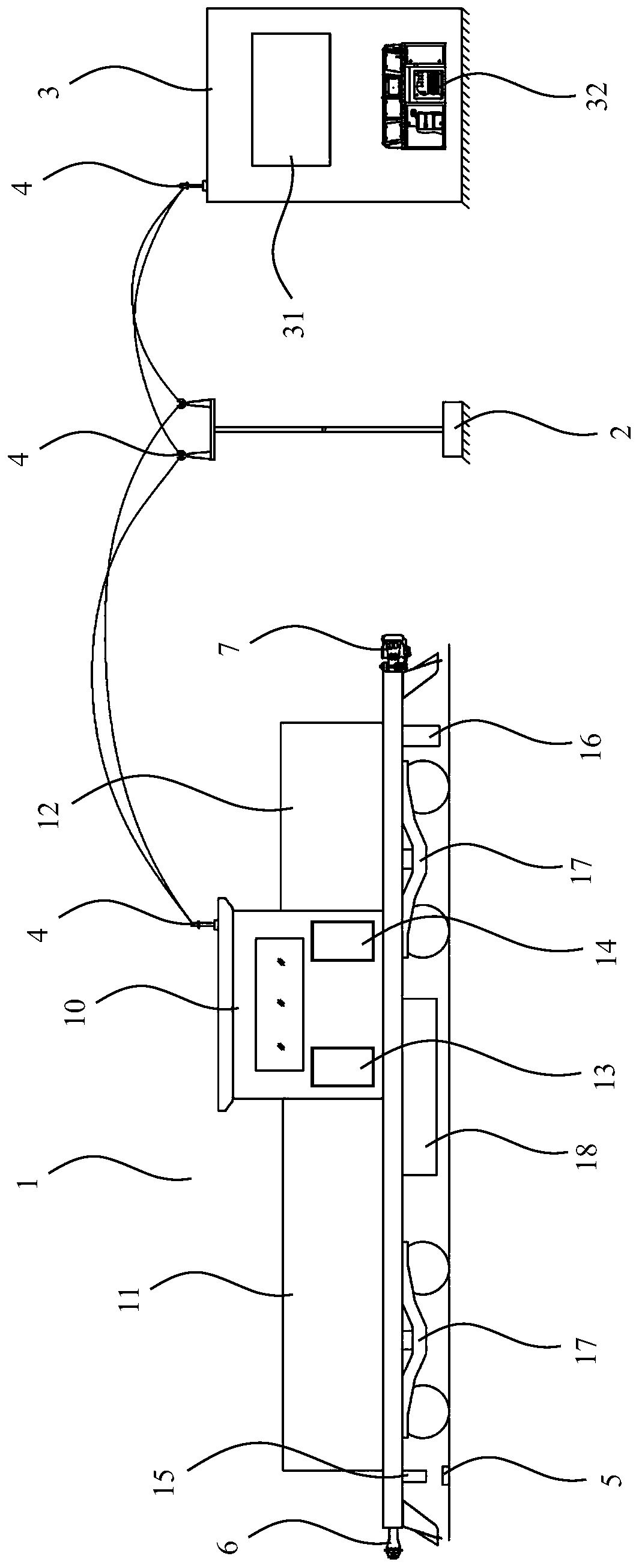
[0080] B) During the test, the first vehicle-mounted network control system 131 arranged on the test drive vehicle 1 recognizes the ground beacon 5 provided on the sleeper 60 through the beacon reading device 15, so as to determine the position of the test drive vehicle 1. Current position, and send a signal to the ground console 32 of the ground control room 3 through the vehicle wireless reconnection unit 142;

[0081] C) The ground network control system 321 installed on t...

Embodiment 3

[0091] as attached figure 1 And attached Figure 5 As shown, an embodiment of an intelligent drive system for a line collision test for realizing the method described in Embodiment 1 specifically includes: a test drive vehicle 1 and a ground control room 3, and the test drive vehicle 1 is used as a rail tractor to pull the vehicle under test 30 Run and complete the crash test. The test driving vehicle 1 is provided with a first vehicle network control system 131 , a vehicle wireless reconnection unit 142 (ie RCMe1 ) and a beacon reading device 15 . During the test, the first vehicle-mounted network control system 131 identifies the ground beacon 5 set on the sleeper 60 through the beacon reading device 15, so as to determine the current position of the test drive vehicle 1, and through the vehicle-mounted wireless reconnection unit 142 sends a signal to the ground console 32 of the ground control room 3. The ground console 32 is provided with a ground network control system...


PUM


Abstract

The invention discloses a railway vehicle line collision test method. When a vehicle under test starts to carry out a collision test, a test driving vehicle is connected with the vehicle under test through a first coupler; the test driving vehicle pushes the vehicle under test to start and accelerate; when the running speed of the test driving vehicle and the running speed of the vehicle under test reach a specified speed, the test driving vehicle and the vehicle under test operate at a constant speed for a period; when the vehicle under test arrives at the position of an unhooking point, a beacon reading device detects the position of a ground beacon, and sends a fixed-point signal to a ground control station; after receiving the fixed-point signal, the ground control station sends an unhooking instruction to the test driving vehicle, and the first coupler is opened; the test driving vehicle starts braking, and the test driving vehicle is separated from the vehicle under test, the vehicle under test performs idle running until arriving at a collision point, and the test driving vehicle gradually decelerates until stopping. With the railway vehicle line collision test method adopted, the technical problems of failure to realize the remote control of an experimental process, low test safety and low stability of an existing line collision test method can be solved.

Description

technical field [0001] The invention relates to the technical field of rail vehicles, in particular to a method applied to rail vehicle line collision tests. Background technique [0002] In the existing rail vehicle crash test, the test vehicle is driven and accelerated by the real automatic power locomotive as the driving device on the fixedly erected track, for example, the test vehicle is pushed and accelerated by the locomotive at the rear of the test vehicle. The locomotive gradually speeds up. When the test vehicle driven by it reaches the preset speed required for the crash test, the locomotive stops speeding up and brakes. The test vehicle slides forward on the track without the driving force of the rear locomotive, and then When a collision occurs with the detection device, the detection device can obtain relevant data of the test vehicle, including the body's concave distortion posture and impact force. In this detection process, the real locomotive is used as th...

Claims


Application Information

Patent Timeline
Patent Type & Authority Applications(China)
IPC IPC(8): G01M17/08B61L3/12
CPCB61L3/12G01M17/08
Inventor 王增宝
Owner ZHUZHOU TIMES ELECTRONICS TECH CO LTD
Why Eureka
Try Eureka