Maximum power tracking control method and system for photovoltaic array

A maximum power tracking, photovoltaic array technology, applied in general control systems, control/regulation systems, photovoltaic power generation, etc., can solve the problems of easy to fall into local optimum, large fluctuation range, large fluctuation range of power curve, etc.

Active Publication Date: 2019-09-27
QINGHAI UNIV FOR NATITIES
View PDF4 Cites 3 Cited by
  • Summary
  • Abstract
  • Description
  • Claims
  • Application Information

AI Technical Summary

Problems solved by technology

[0002] At present, with the wide application of photovoltaic power generation, the tracking method of maximum power point in the process of photovoltaic power generation control has also been extensively studied, including the application of standard particle swarm optimization (PSO) to photovoltaic MPPT, and the use of particle swarm optimization The tracking of the maximum power point, but there are many defects in the application process of the particle swarm algorithm in the tracking of the maximum power point. 1. Before the maximum power is tracked, it is easy to fall into the local extremum or fluctuate greatly after stabilization. In practice, most of the power will be lost. For example, in the document "Application of Particle Swarm Optimization in MPPT Control of Photovoltaic System", Huijing, Wang Sijie, Xie Wei, etc. improved on the basis of traditional PSO, adding particle elimination link, but the power curve fluctuates a lot before it stabilizes, which is easy to cause power loss
2. The problem of initial particle swarm positioning. If the positioning is decentralized, the convergence time of the particle swarm algorithm

Method used


Image

  • Maximum power tracking control method and system for photovoltaic array
  • Maximum power tracking control method and system for photovoltaic array
  • Maximum power tracking control method and system for photovoltaic array

Examples


Embodiment Construction

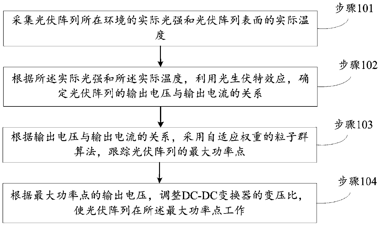
[0079] The technical solutions in the embodiments of the present invention will be clearly and completely described below with reference to the accompanying drawings in the embodiments of the present invention. Obviously, the described embodiments are only a part of the embodiments of the present invention, but not all of the embodiments. Based on the embodiments of the present invention, all other embodiments obtained by those of ordinary skill in the art without creative efforts shall fall within the protection scope of the present invention.

[0080] The purpose of the present invention is to provide a maximum power tracking control method and system for a photovoltaic array, so as to avoid falling into a local optimum during the tracking process, causing power loss, and reducing the tracking time of the maximum power point, so as to achieve multiple extreme values. Fast and efficient search for the maximum power point of a partially shaded photovoltaic array of points.

[...


PUM


Abstract

The invention provides a maximum power tracking control method and system for a photovoltaic array. The tracking control method comprises the following steps: firstly, determining a relationship between an output voltage and an output current of the photovoltaic array by utilizing a photovoltaic effect according to acquired actual light intensity and actual temperature; secondly, based on the relationship between the output voltage and the output current, tracking the maximum power point of the photovoltaic array by adopting an adaptive weight particle swarm algorithm; and finally, adjusting the transformation ratio of a DC-DC converter disposed between the photovoltaic array and the load according to the output voltage of the maximum power point, and enabling the photovoltaic array to work at the maximum power point. According to the method, the particle swarm algorithm with the self-adaptive weight is used for tracking the maximum power point of the photovoltaic array, the power loss caused by falling into local optimum in the tracking process is avoided, the tracking of the first peak power through the particle swarm algorithm in the initialization stage is not needed, and the tracking time of the maximum power point is shortened.

Description

technical field [0001] The invention relates to the technical field of photovoltaic power generation, in particular to a maximum power tracking control method and system of a photovoltaic array. Background technique [0002] At present, with the wide application of photovoltaic power generation, the tracking method of the maximum power point in the photovoltaic power generation control process has also been widely studied, including the application of the standard particle swarm algorithm (PSO) to the photovoltaic MPPT, and the use of particle swarm algorithm to carry out The tracking of the maximum power point, but there are many defects in the application of the particle swarm algorithm in the tracking of the maximum power point. 1. It is easy to fall into a local extreme value before tracking the maximum power or the fluctuation range is large after stabilization. In practice, most of the power will be lost. For example, in the document "Application of Particle Swarm Opti...

Claims


Application Information

Patent Timeline
IPC IPC(8): G05F1/67G05B13/04G05B13/02
CPCG05B13/0265G05B13/042G05F1/67Y02E10/56
Inventor 李明
Owner QINGHAI UNIV FOR NATITIES
Why Eureka
Try Eureka