
Fuel cell fixture convenient for quick disassembly and assembly

A fuel cell and fixture technology, which is applied in fuel cells, circuits, electrical components, etc., can solve problems such as hindering battery performance, easy loosening, and interference with test data, so as to shorten replacement time, improve work efficiency, and improve experimental efficiency. Effect

Active Publication Date: 2019-09-27
SHANDONG JIANZHU UNIV
View PDF6 Cites 2 Cited by
  • Summary
  • Abstract
  • Description
  • Claims
  • Application Information

AI Technical Summary

Problems solved by technology

[0004] 1. Mainly use 4-8 bolts and nuts to lock the upper and lower frames. Not only is the work efficiency low, but also the force is uneven when locking, and it is difficult to control the pre-tightening force, resulting in misalignment or poor contact between the anode plate and the cathode plate. Thus affecting battery performance and test data;
[0005] 2. During long-term use, the fixture is prone to loosening, especially the problem of loose clamping, which has a serious impact on the airtightness of the fuel cell, thereby hindering the performance of the battery, interfering with test data, and affecting the use of the fuel cell
When this happens, it can only be clamped by tightening the bolts and nuts, but the clamping effect of the local force connection method is not ideal
[0006] 3. When replacing different membrane electrodes or flow channel plates, each part needs to be dismantled in turn, the operation process is complicated, and the assembly is time-consuming and laborious;
[0007] 4. It is difficult to ensure the consistency of assembly and the airtightness of fuel cells, which seriously affects the accuracy of single cell test data

Method used


Image

  • Fuel cell fixture convenient for quick disassembly and assembly
  • Fuel cell fixture convenient for quick disassembly and assembly
  • Fuel cell fixture convenient for quick disassembly and assembly

Examples


Embodiment Construction

[0035] The technical solutions in the embodiments of the present application will be clearly and completely described below in conjunction with the accompanying drawings in the embodiments of the present application. Obviously, the described embodiments are only some of the embodiments of the present application, not all of them. Based on the embodiments of the present application, all other embodiments obtained by persons of ordinary skill in the art without making creative efforts belong to the protection scope of the present application.

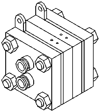
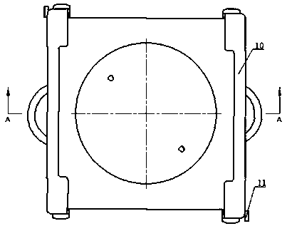
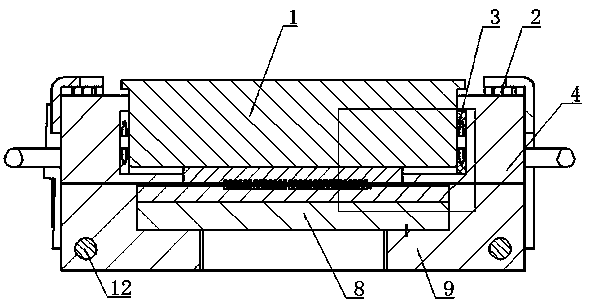
[0036] Such as Figure 2-7 In the shown fuel cell unit, the gas guide piston 1 can move downward along the circular space inside the cathode frame 4 under the action of external force, and press the cathode plate 5 and the membrane electrode 6 tightly. In order to increase the sealing performance between the gas guiding piston 1 and the cathode frame 4, a sealing ring 3 is installed between the first step and the second step of the cathod...


PUM


Abstract

The invention discloses a fuel cell fixture convenient for quick disassembly and assembly. The fuel cell fixture convenient for quick disassembly and assembly comprises a membrane electrode; two sides of the membrane electrode are provided with a cathode plate and an anode plate respectively; one side, far away from the membrane electrode, of the cathode plate is provided with a gas guiding piston; a cathode frame is arranged outside the gas guiding piston and the cathode plate; one side, far away from the membrane electrode, of the anode plate is provided with an anode pad plate; an anode frame is arranged outside the anode pad plate and the anode plate; one side, far away from the cathode plate, of the cathode frame is provided with multiple adjustable screws; the anode frame is hinged with a fixing frame for tightly pressing the cathode frame; and after the fixing frame and the cathode plate are clamped, the outer plane of the adjustable screw is contacted with the inner plane of the fixing frame. The fixture solves the problems of assembly and clamping during the fuel cell testing and production process, and the air tightness of the fixture is improved.

Description

technical field [0001] The invention relates to the field of fuel cells, in particular to a fuel cell clamp that is convenient for quick disassembly. Background technique [0002] Fuel cell is a device that directly converts the chemical energy of fuel into electrical energy. It has become an important new energy development direction in the 21st century due to its advantages such as high power generation efficiency, large specific energy, strong reliability, environmental protection and pollution-free, and fuel diversification. , known as the fourth-generation power generation technology after hydraulic power, thermal power, and nuclear power. Among them, the proton exchange membrane fuel cell has become one of the most widely adaptable fuel cells due to its unique advantages of high power, simple structure, and easy operation. It is currently recognized as one of the preferred energy sources for electric vehicles and stationary power stations. [0003] Since the selection...

Claims


Application Information

Patent Timeline
Patent Type & Authority Applications(China)
IPC IPC(8): H01M8/0273H01M8/0276H01M8/0297
CPCH01M8/0273H01M8/0276H01M8/0297Y02E60/50Y02P70/50
Inventor 郑明刚廉钰弢朱万超
Owner SHANDONG JIANZHU UNIV
Learn More