An energy-saving landfill leachate treatment device

A landfill leachate and treatment device technology, which is applied in waste treatment, transportation and packaging, chemical instruments and methods, etc., can solve the problems of reducing the service life of compression cylinders, high energy consumption, and slow separation rate, etc., so as to reduce working energy Consumption, increase energy saving effect, reduce cost effect

Active Publication Date: 2021-06-22
ANHUI LANDING ENVIRONMENTAL PROTECTION ENERGY TECH
View PDF15 Cites 0 Cited by
  • Summary
  • Abstract
  • Description
  • Claims
  • Application Information

AI Technical Summary

Problems solved by technology

But it has the following disadvantages: in this invention, the garbage is directly poured into the garbage hopper, and the garbage is penetrated into the compression shell through the conveying screw and compressed by the compression cylinder, which cannot effectively crush large pieces of garbage, and the impact force of direct compression is too large , it is easy to reduce the service life of the compression cylinder, and the bagged garbage has not been dismantled, so the liquid in the bagged items cannot be effectively squeezed out during the extrusion process, and the leachate in the garbage cannot be fully collected, and there is still leachate The phenomenon of remaining in the garbage can not make the garbage fully compressed, which affects the compression efficiency of the garbage. At the same time, the garbage and leachate are separated by squeezing out the liquid. The separation rate is slow, the effect is not good, the energy consumption is large, and the cost is relatively high. high

Method used


Image

  • An energy-saving landfill leachate treatment device
  • An energy-saving landfill leachate treatment device
  • An energy-saving landfill leachate treatment device

Examples


Embodiment Construction

[0030] The following will clearly and completely describe the technical solutions in the embodiments of the present invention with reference to the accompanying drawings in the embodiments of the present invention. Obviously, the described embodiments are only some, not all, embodiments of the present invention. Based on the embodiments of the present invention, all other embodiments obtained by persons of ordinary skill in the art without making creative efforts belong to the protection scope of the present invention.

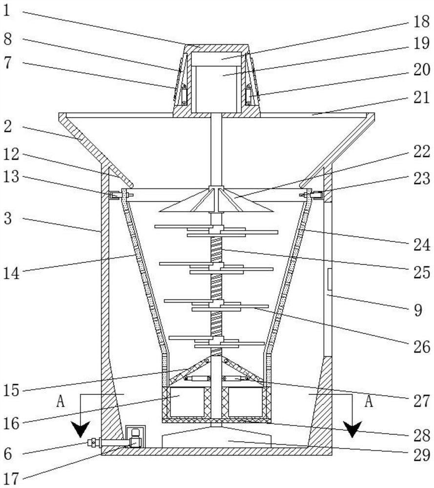
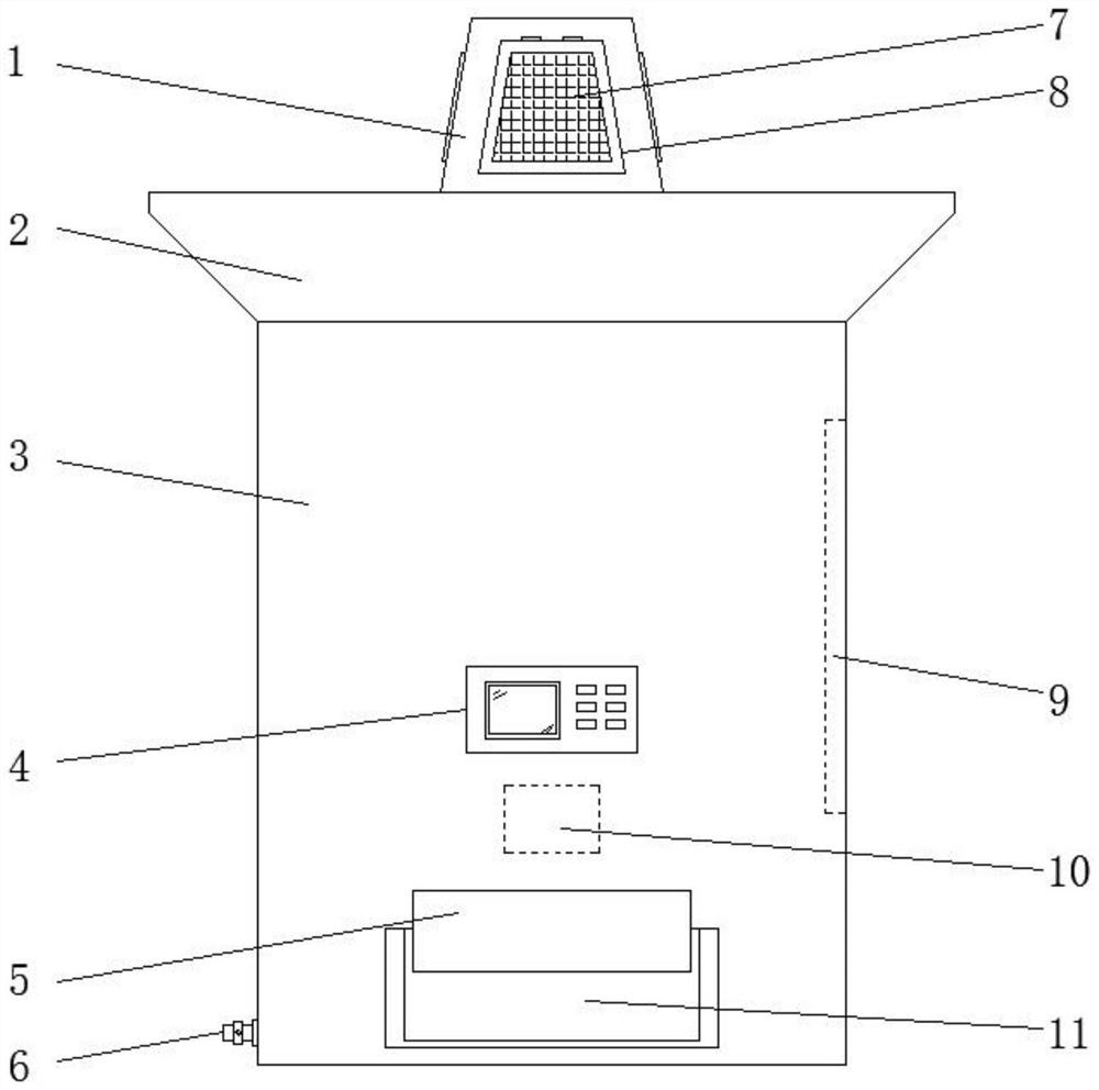
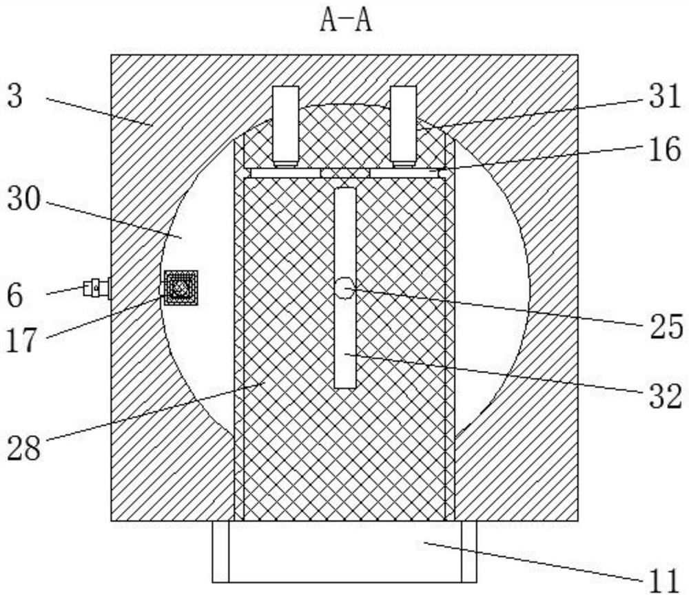
[0031] see Figure 1-5 , an embodiment provided by the present invention: an energy-saving landfill leachate treatment device, comprising a drive seat 1, a feed end 2, a treatment box 3, a garbage discharge port 5 and a liquid separation cylinder 14, and one part of the treatment box 3 The side is hinged with an inspection door 9, and the bottom of the other side of the treatment box 3 is equipped with a liquid outlet pipe 6, and one end of the treatment box 3...


PUM


Abstract

The invention discloses an energy-saving garbage leachate treatment device, which comprises a driving seat, a feed end, a treatment box, a garbage discharge port and a liquid separation cylinder. One side of the treatment box is hinged with an inspection door, and the other side of the treatment box is The bottom of the side is equipped with a liquid outlet pipe, and the top of the treatment box is connected with a feed end, and the center of the top of the feed end is connected with a drive seat, and the top of the feed end on both sides of the drive seat is provided with a feed port. The outer side of the tank is uniformly hinged with an adjustment plate, and solar panels are installed on the adjustment plates. A liquid guide seat is installed at the center of the inner bottom of the treatment box, and a blanking seat is installed inside the treatment box above the liquid guide seat. A liquid separation cylinder is arranged inside the treatment box above the unloading seat. The invention can effectively crush the garbage, and carry out bag-breaking treatment on the bagged garbage, avoid leachate remaining in the garbage, fully separate the garbage and the leachate, improve the separation rate of the garbage and the leachate, and increase the compression rate of the garbage.

Description

technical field [0001] The invention relates to the field of landfill leachate treatment, in particular to an energy-saving landfill leachate treatment device. Background technique [0002] Landfill leachate refers to the moisture contained in the garbage itself in the landfill, the rain and snow water and other moisture entering the landfill, deducting the saturated water holding capacity of the garbage and the covering soil, and passing through the garbage layer and the covering soil. A kind of high-concentration organic wastewater, if discharged directly into the environment without treatment, will cause serious environmental pollution, so landfill leachate treatment is an indispensable work in environmental protection. [0003] In the patent application publication number CN 107827169 A, a leachate treatment device of a garbage transfer station is disclosed, including a leachate treatment, a pump, a fixing seat, a liquid collection chamber, a support seat, a connecting c...

Claims


Application Information

Patent Timeline
Patent Type & Authority Patents(China)
IPC IPC(8): B09B3/00
CPCB09B3/00B09B2101/02Y02W30/20
Inventor 孙翔沈培发朱荣王晓庆刘传伟石金金鄢永恒林娟卓月荣李建华
Owner ANHUI LANDING ENVIRONMENTAL PROTECTION ENERGY TECH
Why Eureka
Try Eureka