Cloth unwinding device

A technology of unwinding device and cloth, which is applied in the direction of winding strips, thin material processing, transportation and packaging, etc., which can solve the problems of affecting the efficiency of unwinding transmission, troublesome operation, time-consuming and laborious operation, and inability to ensure consistency, etc., so as to ensure the work Efficiency and quality, convenient adjustment, and the effect of improving unwinding efficiency

Active Publication Date: 2019-10-01
盐城金云盾网络科技有限公司
View PDF6 Cites 2 Cited by
  • Summary
  • Abstract
  • Description
  • Claims
  • Application Information

AI Technical Summary

Problems solved by technology

[0002] Cloth is required to be used in clothing manufacturing, and it needs to be rolled up neatly so that it can be used in the manufacture of clothing. Therefore, a cloth unwinding device for clothing manufacturing is used. The current unwinding device for cloth for clothing manufacturing has some disadvantages. In the process of unwinding the fabric, it is prone to skew during transmission, which affects the efficiency of unwinding and transmission. In the prior art, limit baffles are generally installed on the fabric roller to position the fabric to avoid skewing, but bolts are usually used for adjustment, which is troublesome to operate. Time-consuming and labor-intensive, or using electrical equipment such as electric push rods, telescopic cylinders, motors, etc. as power to drive the limit plate to move and adjust, but this increases the cost, and the consistency cannot be guaranteed when driving the two limit plates to move and adjust, and deviations are easy to occur , the positioning accuracy is low; and the existing unwinding device manually cuts the cloth, which is inefficient and affects product quality, which needs to be improved

Method used


Image

  • Cloth unwinding device
  • Cloth unwinding device
  • Cloth unwinding device

Examples


Embodiment Construction

[0025] The technical solutions in the embodiments of the present invention will be clearly and completely described below in conjunction with the embodiments of the present invention. Apparently, the described embodiments are only some of the embodiments of the present invention, not all of them. Based on the embodiments of the present invention, all other embodiments obtained by persons of ordinary skill in the art without making creative efforts belong to the protection scope of the present invention.

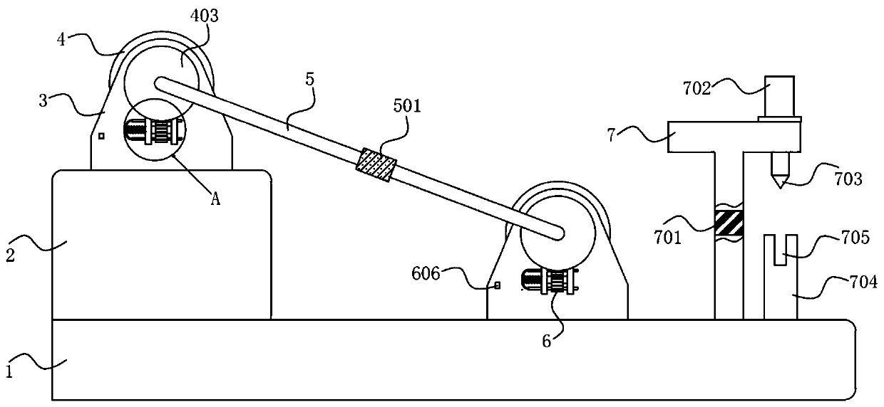
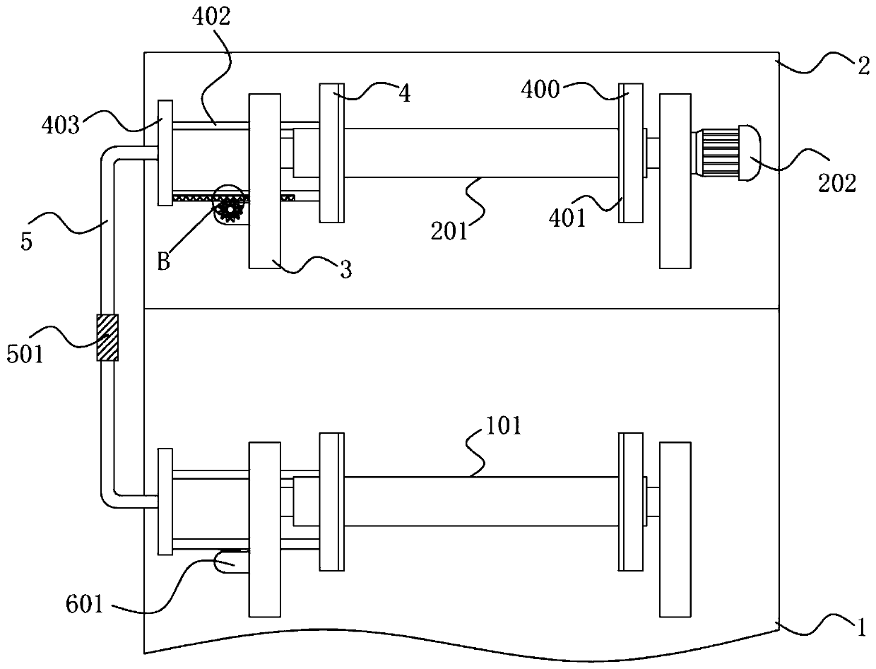
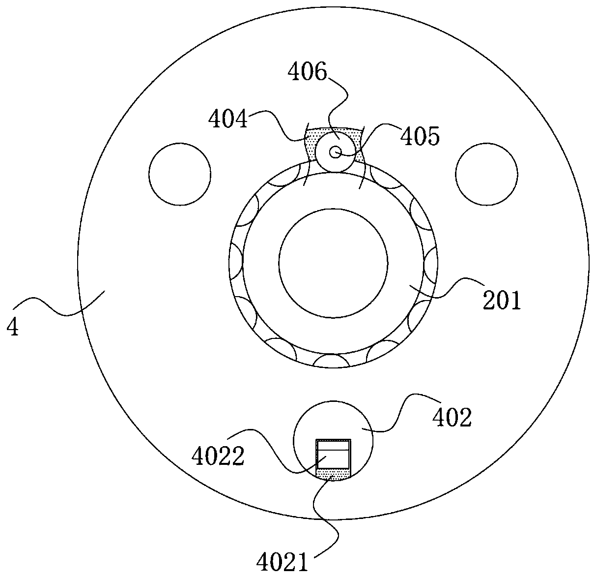
[0026] Such as Figure 1-6 As shown, a cloth unwinding device includes a base 1, and one end of the top of the base 1 is fixedly connected with a fixed seat 2 by bolts, and the fixed seat 2 and the base 1 are fixedly connected with a support seat 3. A conveying guide roller 101 is connected between the support seats 3 of the base 1 through a bearing, and an unwinding roller 201 is connected between the support seats 3 of the fixed seat 2 through a bearing, and one end of the ...


PUM


Abstract

The invention discloses a cloth unwinding device comprising a base. One end of the top of the base is fixedly connected with a fixing seat through a bolt, the fixing seat and the base are both fixedlyconnected with supporting seats, a conveying guide roller is connected between the supporting seats of the base through a bearing, an unwinding roller is connected between the supporting seats of thefixing seat through a bearing, one end of the unwinding roller is fixedly connected with a motor, and the output end of a telescopic cylinder is fixedly connected with a cutting tool. The device effectively ensures the limiting and adjusting consistency in the cloth transmission process, improves the unwinding efficiency, avoids the cloth skew phenomenon, greatly improves the limiting effect on cloth in the transmission process, is accurate in positioning, convenient to adjust, simple in operation and flexible in operation and ensures the work efficiency and quality; and when it is necessaryto cut off the unwinding cloth, the telescopic cylinder is started to drive the cutting tool to move downwards to cut off the cloth placed on a cutting groove, and the cloth unwinding device is convenient to use.

Description

technical field [0001] The invention belongs to the technical field of textile equipment, and in particular relates to a cloth unwinding device. Background technique [0002] Cloth is required to be used in clothing manufacturing, and it needs to be rolled up neatly so that it can be used in the manufacture of clothing. Therefore, a cloth unwinding device for clothing manufacturing is used. The current unwinding device for cloth for clothing manufacturing has some disadvantages. In the process of unwinding the fabric, it is prone to skew during transmission, which affects the efficiency of unwinding and transmission. In the prior art, limit baffles are generally installed on the fabric roller to position the fabric to avoid skewing, but bolts are usually used for adjustment, which is troublesome to operate. Time-consuming and labor-intensive, or using electrical equipment such as electric push rods, telescopic cylinders, motors, etc. as power to drive the limit plate to move...

Claims


Application Information

Patent Timeline
Patent Type & Authority Applications(China)
IPC IPC(8): B65H16/06B65H16/10B65H23/26B65H23/032B65H35/06
CPCB65H16/06B65H16/103B65H23/0324B65H23/26B65H35/06B65H2701/1133B65H2701/174
Inventor 李敏
Owner 盐城金云盾网络科技有限公司
Why Eureka
Try Eureka