Printing and dyeing industrial wastewater treatment apparatus

A technology for treating device and industrial wastewater, which is applied in multi-stage water treatment, water/sewage treatment, neutralized water/sewage treatment, etc., which can solve the problem of unsatisfactory wastewater treatment and purification effect, the inability of additives to achieve the treatment effect, and the reduction of pipeline flow. and other problems, to achieve the effect of high safety discharge passing efficiency, good automatic effect and good treatment effect.

Active Publication Date: 2019-10-08
天津安禹水利工程有限公司
View PDF9 Cites 3 Cited by
  • Summary
  • Abstract
  • Description
  • Claims
  • Application Information

AI Technical Summary

Problems solved by technology

[0003] The current printing and dyeing industrial wastewater treatment devices are various, and different methods are used to treat and purify the printing and dyeing industrial wastewater, but the treatment and purification effect of the wastewater is not ideal, and the treatment process is always accompanied by various problems, such as Adding solid additives will cause a large amount of physicochemical sludge to be generated during wastewater treatment, which may block the pipeline and reduce the flow rate of the pipeline, or directly damage the device; The problem is that it is impossible to accurately add additives when the device is running, and stop adding additives when the device stops. Too many additives will cause waste of cost, and too little additives will not achieve the treatment effect.

Method used


Image

  • Printing and dyeing industrial wastewater treatment apparatus
  • Printing and dyeing industrial wastewater treatment apparatus
  • Printing and dyeing industrial wastewater treatment apparatus

Examples


Embodiment Construction

[0028] In order to enable those skilled in the art to better understand the present invention, the technical solutions of the present invention are further described below with reference to the accompanying drawings and embodiments.

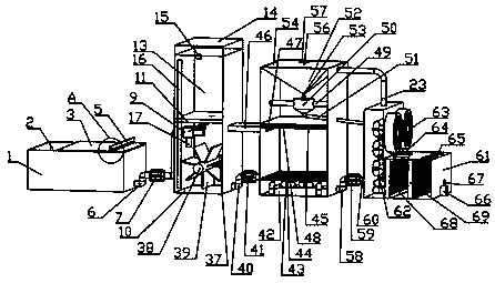
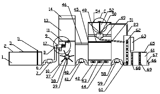
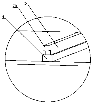
[0029] 2. If figure 1 , figure 2 , image 3 , Figure 4 , Figure 5As shown, a printing and dyeing industrial wastewater treatment device of the present invention includes a wastewater tank 1, and is characterized in that: the wastewater tank 1 includes a water inlet 2 and a wastewater tank cover 3, and the wastewater tank cover 3 is connected with an outer convex groove 4, and the outer convex and concave A filter screen 5 is placed in the tank 4, the output end of the waste water tank 1 is connected with a first pipeline 6, the first pipeline 6 is connected with a first water pump 7 and a first one-way valve 8, and the output end of the first pipeline 6 is connected with a hydraulic box 9. The hydraulic box 9 is connected with a mixing box...


PUM


Abstract

The invention discloses a printing and dyeing industrial wastewater treatment apparatus. The apparatus comprises a waste water tank, wherein the waste water tank is connected with a water inlet, a waste water tank cover, an outer convex concave groove, a filtering net, a first pipeline, a first water pump, a first one-way valve, a water pressure box and a mixing tank, the water pressure box is connected with a water outlet pipe, fixing columns, a first spring fixing tray, a first spring, a flexible bladder, a push block, round holes, a guide column and a position-limiting baffle block, the upper side of the push block is provided with a first connecting plate, a first supporting cylinder, a second connecting plate, a rectangular sliding groove, a rectangular supporting strip, a third connecting plate, a second supporting cylinder, a cylindrical plug, a second spring, a second spring fixing tray and supporting strips, the mixing tank is connected with a partition plate, a material discharge hole, a reagent storage tank, a reagent storage tank cover, a buckle, a visible strip, a fixing groove, a rotating shaft, stirring blades, a second pipeline, a second water pump, a heating tank and a filtering tank, and the filtering tank is equipped with a row pipe, a water conveying pipe, a gas pipe, air coolers, a filler port, air outlets, a drain pipe, a manual valve, a first activated carbon layer and a second activated carbon layer.

Description

technical field [0001] The invention belongs to the field of wastewater treatment devices, and in particular relates to a wastewater treatment device for printing and dyeing industries. Background technique [0002] The wastewater from the printing and dyeing industry has the characteristics of large water volume, complex composition, and serious environmental pollution. At present, the domestic treatment of such wastewater requires that the printing and dyeing wastewater be treated to meet the standards of "GB / T4287-92" and then discharged. This requires the use of wastewater treatment plants. [0003] The current printing and dyeing industrial wastewater treatment devices are various, and different methods are used to treat and purify the printing and dyeing industrial wastewater. The addition of solid additives will cause a large amount of physicochemical sludge to be produced during the wastewater treatment process, which will block the pipeline and reduce the pipeline ...

Claims


Application Information

Patent Timeline
Patent Type & Authority Applications(China)
IPC IPC(8): C02F9/10C02F101/30
CPCC02F9/00C02F1/001C02F1/66C02F1/048C02F1/043C02F1/283C02F2101/308C02F2201/002C02F2201/004C02F2301/066C02F2303/02C02F2301/08C02F2303/14C02F2303/16
Inventor 杨金华
Owner 天津安禹水利工程有限公司
Why Eureka
Try Eureka