Eureka AIR delivers breakthrough ideas for toughest innovation challenges, trusted by R&D personnel around the world.

Milling machine

A milling machine and milling technology, which is applied in the field of machine tools, can solve the problems that the clamping components cannot rotate and the application range is small, and achieve the effect of reducing the cleaning burden, wide application range and high cleaning efficiency

Active Publication Date: 2019-10-11
浙江成洲合金工具有限公司
View PDF8 Cites 1 Cited by
  • Summary
  • Abstract
  • Description
  • Claims
  • Application Information

AI Technical Summary

Problems solved by technology

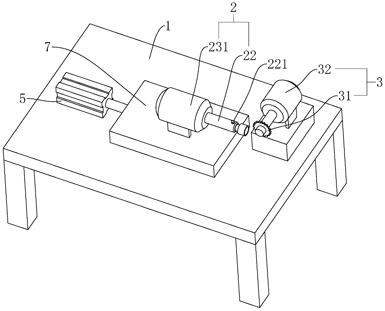
[0004] However, the clamping assembly in the above milling machine can only move linearly with the moving plate under the action of the push cylinder, and the clamping assembly cannot rotate relative to the milling assembly, so that the milling cutter can only form a groove with a fixed angle on the workpiece when grinding the workpiece. groove
The above-mentioned milling machine cannot be used to process grooves with different angles on the workpiece, the scope of application is small, and needs to be improved

Method used


Image

  • Milling machine
  • Milling machine
  • Milling machine

Examples


Embodiment Construction

[0037] The present invention will be described in further detail below in conjunction with the accompanying drawings.

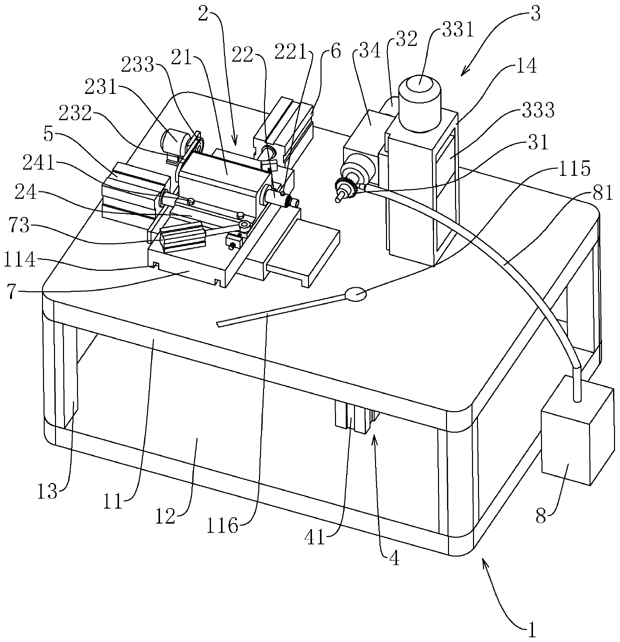
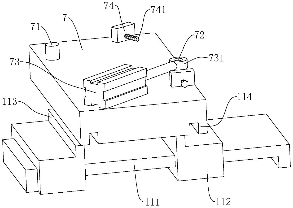
[0038] This embodiment discloses a milling machine, such as figure 2 , Figure 5 As shown, it includes a frame 1, a clamping assembly 2 and a milling assembly 3. The frame 1 includes a workbench 11 and a fixed plate 12 parallel to each other and support rods 13 fixed at the four corners of the workbench 11. The fixed plate 12 is located on the workbench 11. the underside of the A sliding seat 111 is fixed on the workbench 11 , and the upper side of the sliding seat 111 is slidingly provided with a moving plate 7 . The moving plate 7 is rotatably connected with a mounting plate 24 , and the clamping assembly 2 is mounted on the mounting plate 24 . The milling assembly 3 includes a milling cutter 31 , a driving motor 32 and a lifting assembly 33 , the output shaft of the driving motor 32 is fixedly connected to the milling cutter 31 , and the lifting assembl...


PUM


Abstract

The invention relates to the technical field of machine tools, and discloses a milling machine. According to the technical scheme, the milling machine comprises a machine frame, a clamping assembly and a milling assembly, wherein a pushing air cylinder is arranged on the machine frame, the machine frame is connected with a moving plate in a sliding mode, a piston rod of the pushing air cylinder isfixedly connected with the moving plate and drives the moving plate to move towards one side close to the milling assembly, and the moving plate is rotationally connected with a mounting plate through a rotating shaft; the clamping assembly comprises a mounting box arranged on the mounting plate, a mounting shaft rotationally connected with the mounting box and a rotating assembly which drives the mounting shaft to rotate, a workpiece is mounted on the mounting shaft, a driving cylinder is mounted on the moving plate, a driving ring is connected to a piston rod of the driving cylinder, and afixing shaft rotationally connected with the driving ring is fixed on the mounting plate; and the milling assembly comprises a milling cutter, a driving motor used for driving the milling cutter to rotate, and a lifting assembly used for driving the milling cutter to ascend and descend. The milling machine has the advantages that grooves with different angles can be machined on the workpiece, andthe application range is wide.

Description

technical field [0001] The present invention relates to the technical field of machine tools, more specifically it relates to a milling machine. Background technique [0002] A milling machine mainly refers to a machine tool that uses a milling cutter to process various surfaces of a workpiece. Usually, the milling cutter uses rotational motion as the main motion, and the movement of the workpiece and the milling cutter is the feed motion. It can process planes, grooves, various curved surfaces, gears, etc. . [0003] In the prior art, such as figure 1 A milling machine shown includes a frame 1 , a clamping assembly 2 and a milling assembly 3 . A push cylinder 5 is installed on the frame 1 , and a moving plate 7 is connected to the piston rod of the push cylinder 5 . The clamping assembly 2 includes a rotating motor 231 and a mounting shaft 22 fixedly connected to the output shaft of the rotating motor 231. The rotating motor 231 is installed on the moving plate 7, and the...

Claims


Application Information

Patent Timeline
Patent Type & Authority Applications(China)
IPC IPC(8): B23C1/02B23Q11/10
CPCB23C1/02B23Q11/10
Inventor 李高书蔡程
Owner 浙江成洲合金工具有限公司
Why Eureka
Eureka Blog
Learn More