Location control method for strip head of thin strip steel

A positioning control, thin strip technology, applied in the direction of manufacturing tools, auxiliary devices, auxiliary welding equipment, etc., can solve the problem of no control method for the length of the strip head.

Active Publication Date: 2019-10-11
SHANGHAI MEISHAN IRON & STEEL CO LTD
View PDF7 Cites 8 Cited by
  • Summary
  • Abstract
  • Description
  • Claims
  • Application Information

AI Technical Summary

Problems solved by technology

[0004] 1) After the thickness and width specifications of the feeding strip steel change, the feedback value of the encoder deviates from the actual value. The reason is that the thickness of the strip steel specification changes. It is also increasing. When the downforce of the pinch roller remains unchanged, the pinch force of the pinch roller to the strip also increases, the friction between the roller and the strip also increases, and the inertial force of the operation also increases. These points The problem is that the distance from the front grating of the welding machine to the center...

Method used


Image

  • Location control method for strip head of thin strip steel
  • Location control method for strip head of thin strip steel
  • Location control method for strip head of thin strip steel

Examples


Embodiment

[0030] A method for controlling the positioning of a thin strip steel strip head includes the following steps:

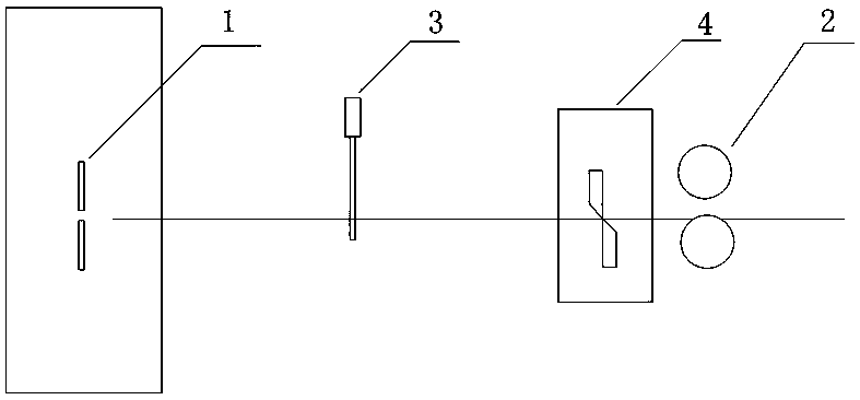
[0031] 1) Such as figure 1 with figure 2 As shown, the welding machine 1 is installed, the pinch roller device 2 is installed at the side of the entrance channel of the welding machine 1, the grating detector 3 is installed between the pinch roller and the welding machine 1, and the grating detector 3 and the welding machine 1 are set The distance between them is Kcm.

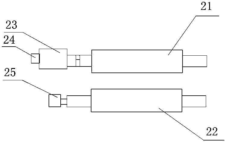
[0032] The pinch roller device 2 includes an upper pressure roller 21, a lower roller 22, a motor 23 connected to one end of the upper pressure roller, and a motor tail encoder 24 connected to the motor. At least one end of the upper pressure roller 21 is provided with a power cylinder. 23 By controlling the power cylinder to make the upper pressure roller 21 fall and lift, a lower roller encoder 25 is installed on the shaft end of the lower roller 22;

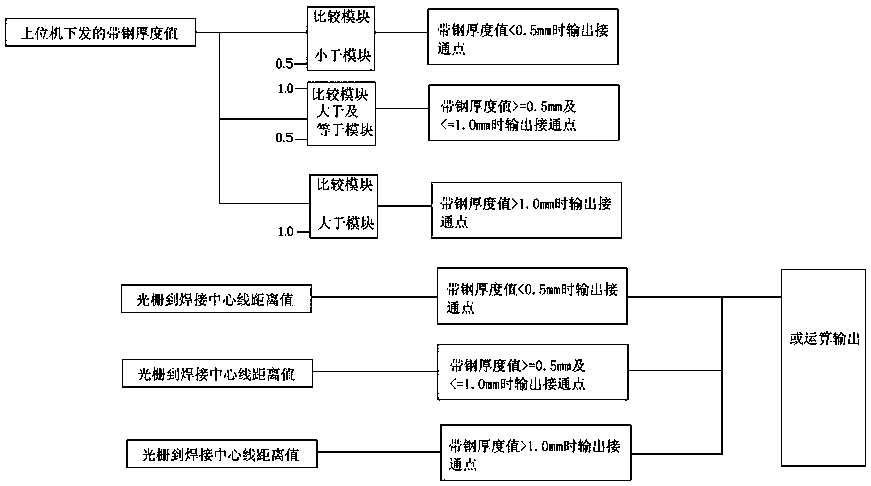
[0033] 2) Such as image 3 As shown, there are thr...


PUM

PropertyMeasurementUnit
Thicknessaaaaaaaaaa
Thicknessaaaaaaaaaa
Thicknessaaaaaaaaaa

Abstract

The invention discloses a location control method for a strip head of thin strip steel, and belongs to the technical field of automatic control. The method comprises the following steps: 1) a weldingmachine, a pinch roll device and an optical grating detector are installed, and the pinch roll device comprises an upper press roll, a lower roll, a motor, a motor tail coder, a power cylinder and a lower roll coder; 2) three thickness specification interval sections of the strip steel are divided and input into a main-line PLC, the upper press roll is controlled to fall off by the main-line PLC until the strip steel is clamped between the upper press roll and the lower roll by virtue of a set clamping force separately; and 3) the running speed of the motor is calculated through the motor tailcoder, the strip steel is conveyed at a speed V1, when the optical grating detector detects the strip steel, the strip steel is conveyed at a speed V2, and meanwhile, the lower roll coder installed on the lower roll starts to calculate the length L of the strip steel passing through the optical grating detector, and location for the strip head is completed. According to the method, the distance error of the strip head at a welding stopping position is reduced, so that the compensation accuracy is increased; and the method is completely feasible, and capable of achieving a good effect.

Description

Technical field [0001] The invention relates to a method for controlling the positioning of a thin strip steel head, in particular to a method for controlling the positioning of a thin strip steel head during welding at a continuous production line welding machine, and belongs to the technical field of automatic control. Background technique [0002] According to the applicant’s understanding, in the actual production of the hot-dip galvanizing line and the hot-dip galvanizing line of the cold rolling plant, since the thickness of the galvanizing line of the cold rolling plant is 0.28 to 1.2mm and the width is 700 to 1250mm, the applicant is producing the above For thin-gauge strip steel with steel thickness, the head of the strip is welded and positioned at the welding machine when the material is loaded. Inaccurate positioning often occurs, and the time is short. It is easy to carry out cutting and welding at the welding machine. If the welding fails, re-cutting and then weldin...

Claims


Application Information

Patent Timeline
IPC IPC(8): B23K37/00B23K37/047
CPCB23K37/00B23K37/047
Inventor 苏广磊李明
Owner SHANGHAI MEISHAN IRON & STEEL CO LTD
Why Eureka
Try Eureka