Multi-spindle glass machining center

A machining center and multi-spindle technology, which is applied in the field of CNC machine tools, can solve the problems of high cost and large size, and achieve the effect of low cost, small size and improved processing efficiency

Inactive Publication Date: 2019-10-11
SHENZHEN CREATE CENTURY MACHINERY
View PDF12 Cites 0 Cited by
  • Summary
  • Abstract
  • Description
  • Claims
  • Application Information

AI Technical Summary

Problems solved by technology

[0003] At present, the common multi-spindle glass processing centers in the market are mainly 2-axis, 3-axis, 4-axis, etc. with linearly distributed spindles. Due to structural constraints, the more spindles, the larger the required external dimensions and relatively high cost.

Method used


Image

  • Multi-spindle glass machining center
  • Multi-spindle glass machining center
  • Multi-spindle glass machining center

Examples


Embodiment 1

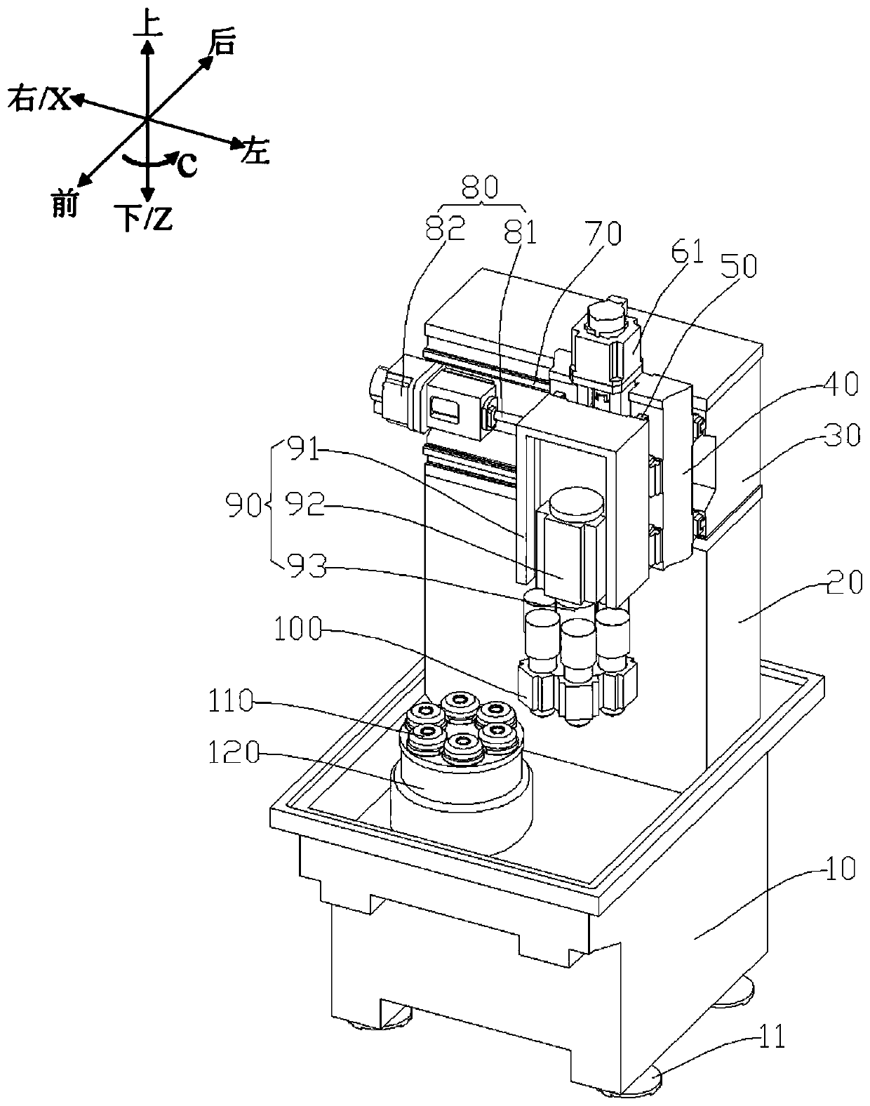
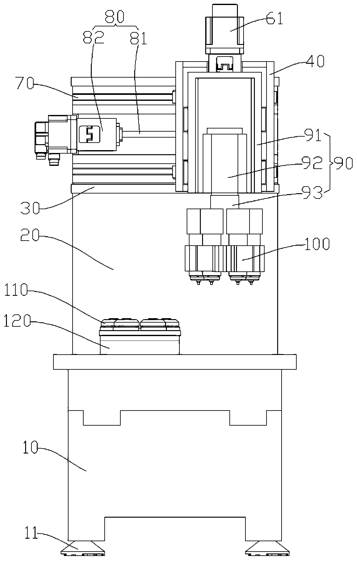
[0029] The glass processing center in this embodiment includes a bed 10 with a processing table base 120, a column 20 on the bed 10, a beam 30 with an X-axis guide rail 70 on the column 20, and a sliding The X-axis slide plate 40 with the Z-axis guide rail 50 on the X-axis guide rail 70, the spindle installation box 90 slidingly arranged on the Z-axis guide rail 50, also includes at least three processing tables 110, at least three processing spindles 100, X-axis drive Mechanism 80, Z-axis driving mechanism, and C-axis driving mechanism.

[0030] Such as figure 1 As shown, the definition of the glass processing center includes a horizontal X-axis, a vertical Z-axis and a C-axis where the processing table 110 rotates. The processing tables 110 are arranged on the processing table base 120 and distributed in the circumferential direction, and are used for clamping workpieces. The processing spindles 100 are installed on the spindle installation box 90, corresponding to the pro...

Embodiment 2

[0041] Example 2, such as figure 1 As shown, the glass processing center in this embodiment has six processing spindles 100 and six processing tables 110 corresponding to the processing spindles 100 . The six processing tables 110 are distributed in a circle and evenly arranged on the base 120 of the processing tables. The six processing spindles 100 correspond to the six processing tables 110 , are distributed in a circle, and are evenly distributed on the spindle installation box 90 . Simultaneous processing of six spindles improves work efficiency.

Embodiment 3

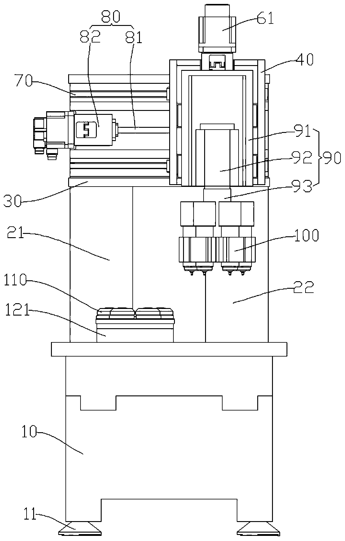
[0042] Example 3, such as figure 2 As shown, the glass processing center in this embodiment has a fourth driving mechanism 94 . The spindle installation box 90 includes a fourth driving mechanism 94 , a central shaft 93 and a box body 91 . The output end of the fourth driving mechanism 94 protrudes outside the box body 91 of the spindle installation box 90 in the negative direction of the Z axis. The processing spindles 100 are distributed in a circle and evenly arranged on the outer peripheral wall of the central shaft 93 . The fourth driving mechanism 94 is used to drive the central shaft 93 to rotate and drive the processing spindles 100 to revolve around the central shaft 93 at a low speed. A fourth drive mechanism 94 is provided in the spindle installation box 90 for driving the processing spindle 100 to rotate around the central axis 93 to increase the processing flexibility of the glass processing center.


PUM


Abstract

The invention provides a multi-spindle glass machining center. The center comprises a bed body provided with a machining table base, a stand column arranged on the bed body, a cross beam which is arranged on the stand column and provided with an X-axis guide rail, an X-axis sliding plate which is arranged on the X-axis guide rail in a sliding mode and is provided with a Z-axis guide rail and a spindle mounting box arranged on the Z-axis guide rail in a sliding mode, and further comprises at least three machining tables, at least three machining spindles, an X-axis driving mechanism, a Z-axis driving mechanism and a C-axis driving mechanism. The machining tables are all arranged on the machining table base, are distributed in the circumferential direction and are used for clamping workpieces. The machining spindles are all installed on the spindle mounting box, correspond to the machining tables and are distributed in the circumferential direction. The X axis, the Z axis and the C axisare linked so that the machining spindles can simultaneously machine the workpieces clamped on the machining tables. The circumferential-distributed multi-axis multi-station machine type can overcomethe structural limitation and disadvantages of linear distribution, the required appearance size is small, the cost is low, the multiple spindles simultaneously conduct machining, so that the machining efficiency is improved.

Description

technical field [0001] The invention relates to the technical field of numerical control machine tools, in particular to a multi-spindle glass processing center. Background technique [0002] With the rapid development of my country's 3C product consumption market and the wide application of glass, ceramics, sapphire and other materials in 3C products, the processing demand of glass products is becoming more and more vigorous. [0003] At present, the common multi-spindle glass processing centers in the market are mainly 2-axis, 3-axis, 4-axis, etc. with linearly distributed spindles. Due to structural limitations, the more spindles, the larger the required external dimensions, and the relatively high cost. Contents of the invention [0004] Based on this, it is necessary to provide a multi-spindle glass processing center with small dimensions and relatively low cost. [0005] A multi-spindle glass processing center, comprising a bed with a processing table base, a column...

Claims


Application Information

Patent Timeline
IPC IPC(8): B24B27/06B24B41/06B24B47/20B28D1/18B28D1/22B28D7/04B28D7/00
CPCB24B27/06B24B41/06B24B47/20B28D1/18B28D1/22B28D7/005B28D7/04
Inventor 叶李生段周波
Owner SHENZHEN CREATE CENTURY MACHINERY
Why Eureka
Try Eureka