
Connecting method and structure of carbon fiber reinforced composite part and metal part and automobile

A technology for reinforcing composite materials and connecting methods, which is applied in the assembly field of the automotive field, can solve problems such as insufficient connection, stress concentration, and damage to fiber continuity, and achieve the effect of improving bonding strength, avoiding stress concentration, and reducing fiber damage.

Inactive Publication Date: 2019-10-11
ZOTYE INT AUTOMOBILE TRADING CO LTD
View PDF2 Cites 3 Cited by
  • Summary
  • Abstract
  • Description
  • Claims
  • Application Information

AI Technical Summary

Problems solved by technology

Among them, adhesive bonding is used for parts that do not require high connection strength, such as body panels. The adhesive bonding structure is prone to aging due to environmental influences and has poor peeling resistance; the mechanical connection has high connection strength and is relatively reliable, and can be used for structural bearings. Force parts, but this connection method needs to open holes in CFRP, destroying the continuity of fibers and affecting the overall performance of CFRP, and stress concentration is prone to occur around the holes
The existing hybrid connection combines the advantages of adhesive bonding and mechanical connection, but the use of fasteners such as rivets and bolts also requires opening holes in CFRP, causing stress concentration problems
There are obvious deficiencies in the connection between CFRP parts and metal parts in the prior art

Method used


Image

  • Connecting method and structure of carbon fiber reinforced composite part and metal part and automobile
  • Connecting method and structure of carbon fiber reinforced composite part and metal part and automobile
  • Connecting method and structure of carbon fiber reinforced composite part and metal part and automobile

Examples


Embodiment Construction

[0023] Below with reference to the accompanying drawings, through the description of the embodiments, the specific embodiments of the present invention, such as the shape, structure, mutual position and connection relationship between the various parts, the role and working principle of the various parts, etc., will be further described. Detailed instructions:

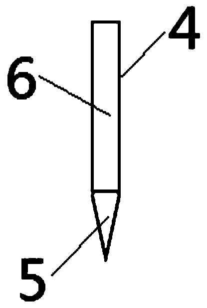
[0024] as attached figure 1 - attached image 3As shown, the present invention is a connection structure between a carbon fiber reinforced composite material part and a metal part, and the described carbon fiber reinforced composite material part and metal part connection structure includes a carbon fiber reinforced composite material part 1, an adhesive film layer 2, a metal part 3, a metal Rod 4, the surface of one side of the adhesive film layer 2 is fixedly connected with the surface of the carbon fiber reinforced composite material part 1, the other side surface of the adhesive film layer 2 is fixedly connected w...


PUM

PropertyMeasurementUnit
thicknessaaaaaaaaaa
diameteraaaaaaaaaa

Abstract

The invention provides a connecting method and structure of a carbon fiber reinforced composite part and a metal part. The connecting method of the carbon fiber reinforced composite part and the metalpart includes the steps that an adhesive film layer (2) is laid on the surface of the metal part (3), and multiple carbon fiber reinforced composite prepreg layers (7) are laid on the adhesive film layer (2); each metal rod (4) penetrates through the multiple carbon fiber reinforced composite prepreg layers (7), the adhesive film layer (2) and the metal part (3); and the structures of the carbonfiber reinforced composite part and the metal part are transferred into a forming die to be heat-cured, and the multiple carbon fiber reinforced composite prepreg layers (7) are heat-cured to form thecarbon fiber reinforced composite part (1). According to the connecting method of the carbon fiber reinforced composite part and the metal part, the interlayer strength of a carbon fiber reinforced composite can be improved, the stripping-resistant capacity of the adhesive film layer for connecting the carbon fiber reinforced composite with the metal part is improved, and the bearing capacity isimproved.

Description

technical field [0001] The invention relates to assembly technology in the field of automobiles, in particular to a method for connecting a carbon fiber reinforced composite material part and a metal part, a connection structure and an automobile using the connection method. The connection method and connection structure described in the present invention can be used in the manufacture of multiple parts on automobiles Background technique [0002] With the increasing global environmental pollution and energy crisis, energy conservation and emission reduction has become an important issue for the sustainable development of the global automotive industry. As an important means of energy saving and emission reduction, lightweight has been highly valued by various automobile companies, and it is also an effective means for them to improve their competitiveness. Carbon fiber reinforced composite material (English full name is Carbon Fiber Reinforced Polymer / Plastic, abbreviated ...

Claims


Application Information

Patent Timeline
Patent Type & Authority Applications(China)
IPC IPC(8): B29C70/78B29C70/30
CPCB29C70/30B29C70/78
Inventor 张然然熊建民王方玉陈伊宁苏一畅贺丽丽顾时茂罗艳孟
Owner ZOTYE INT AUTOMOBILE TRADING CO LTD
Learn More