Hydraulic transmission speed change system

A technology of hydraulic transmission and transmission fluid, which is applied in transmission devices, vehicle gearboxes, fluid transmission devices, etc. It can solve the problems of no specific description of the shape and installation position, no specific description of the specific structure, etc., and achieve compact structure and strong adaptability , a wide range of effects

Inactive Publication Date: 2019-10-11
董鹏
View PDF3 Cites 1 Cited by
  • Summary
  • Abstract
  • Description
  • Claims
  • Application Information

AI Technical Summary

Problems solved by technology

[0006] Authorized announcement number: CN105711581B's invention "A Control Method for a Continuously Variable Tractor Control System" is also a research on the control method of the variable speed system. There is no specific description of the specific structure of the "variable pump-quantitative motor hydraulic speed regulating mechanism" in the full text. For the variable pump, the article only mentions changing the flow rate by changing the inclination angle of the swash plate, but for the fixed-quantity motor, the article does not describe its shape, structure, composition, characteristics, and installation position in detail.

Method used


Image

  • Hydraulic transmission speed change system
  • Hydraulic transmission speed change system
  • Hydraulic transmission speed change system

Examples


Embodiment 1

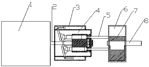
[0032] Embodiment 1: A hydraulic transmission transmission system of the present invention is used to manufacture an automatic transmission for vehicles.

[0033] In this embodiment, a straight-axis swash plate rotary cylinder type 11-column piston pump is used as a variable displacement piston pump, with a nominal displacement of 160ml / r and a maximum torque of 800Nm. 21 degrees, the swash plate inclination adjustment mechanism is hydraulic adjustment. The cycloidal hydraulic motor adopts a triangular rotor cycloidal hydraulic motor with a nominal displacement of 200ml / r and a maximum torque of 770Nm.

[0034] The variable displacement plunger pump includes housing, back cover, swash plate support seat, swash plate, spherical bushing, sliding shoe, return plate, cylinder block, flow plate, plunger, variable piston rod, variable piston, upper adjustment rod, lower Adjustment rod, upper return spring and lower return spring.

[0035] Among them, there is a shaft hole in the f...

Embodiment 2

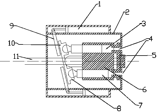
[0039] Embodiment 2: Utilize a kind of hydraulic transmission speed change system of the present invention to manufacture bicycle speed change and transmission system.

[0040] In this embodiment, a straight-axis swash plate rotary cylinder type 5-column plunger pump is used as a variable displacement piston pump, with a nominal displacement of 25ml / r, a maximum torque of 130Nm, and a swash plate inclination angle perpendicular to the axial direction. 19 degrees, the swash plate inclination adjustment mechanism is adjusted by a spring cable. The cycloidal hydraulic motor adopts a triangular rotor cycloidal hydraulic motor with a nominal displacement of 20ml / r and a maximum torque of 140Nm.

[0041] The variable displacement plunger pump consists of a casing, a rear cover, a transmission shaft, a swash plate support seat, a swash plate, a spherical bush, a sliding shoe, a return plate, a cylinder block, a flow plate, a plunger, a return spring and a pull wire.

[0042] The var...


PUM


Abstract

The invention discloses a hydraulic transmission speed change system. According to a power transmission speed change system, the gear shifting speed change can be truly realized and the transmission direction of the force can be changed on the basis that continuous stable transmission of power, the structure is simple and the manufacturing cost is low. According to the hydraulic transmission speedchange system, a variable plunger pump is adopted to convert mechanical power into hydraulic power, and then a rotary wheel line type hydraulic motor is used for converting the hydraulic power into the mechanical power. By adjusting the inclination angle of a swash plate, the flow rate of a transmission liquid can be adjusted, the rotating speed and the torque of the power output can be changed,and therefore the purpose of speed change is achieved. Due to the fact that the inner cavity of the variable plunger pump and the inner cavity of the rotary wheel line type hydraulic motor are both continuous closed lines (surfaces) so that the mechanical efficiency of the system can reach a very high level.

Description

technical field [0001] The invention belongs to the field of power transmission and speed change, in particular to a hydraulic transmission speed change system. Background technique [0002] In existing power transmission and speed change technologies, gears, transmission shafts, chains, belts, etc. are mostly used to transmit power, and gears or cones with different gear ratios are used to realize speed change. For example, in the field of automotive transmissions, regardless of manual gearboxes, dual-clutch gearboxes, AT gearboxes, and CVA gearboxes, to achieve shifting and shifting, the clutch can only be used to cut off the power transmission or the hydraulic torque converter can be used to flexibly connect the power. Can not really realize the stable and continuous transmission of power. [0003] In the field of bicycles, with the development of the sharing economy, there are more and more shared bicycles, but almost all shared bicycle companies can only provide the pu...

Claims


Application Information

Patent Timeline
Patent Type & Authority Applications(China)
IPC IPC(8): F16H39/10B62M19/00
CPCB62M19/00F16H39/10F16H2039/105
Inventor 董鹏
Owner 董鹏
Why Eureka
Try Eureka