Efficient sludge drying system for sewage treatment

A sludge drying and sewage treatment technology, applied in water/sludge/sewage treatment, sludge treatment, energy and waste water treatment, etc., can solve the problems of poor automation, inconvenient transportation, large consumption of filter cloth, etc., to achieve convenient and neat Stacking and storage, convenient transportation and storage, smooth and continuous conveying effect

Active Publication Date: 2022-04-12
HUNAN ZHONGTUO ENVIRONMENTAL ENG CO LTD
View PDF6 Cites 2 Cited by
  • Summary
  • Abstract
  • Description
  • Claims
  • Application Information

AI Technical Summary

Problems solved by technology

Sludge with 80% water content has a strong odor and putrid smell, which is inconvenient to transport, easily causes environmental pollution, and consumes energy. Moreover, the content of solid impurities in the wastewater generated during the primary drying process is still high, which is not conducive to Subsequent sewage treatment
As a commonly used sludge drying equipment, the filter press is easy to block the feed port of the filter frame, the filter cake is not easy to take out, cannot run continuously, the processing capacity is small, the working pressure is low, and the square plate of ordinary material is not pressure-resistant and easy to break. The filter cloth consumes a lot, and the plate and frame are difficult to be unattended, and the filter cloth often needs to be cleaned manually
At the same time, the plate and frame filter press needs to be guarded by a special person, with poor automation, many moving parts, instability, low equipment investment, difficult maintenance, complicated operation, special management, and short service life.

Method used


Image

  • Efficient sludge drying system for sewage treatment
  • Efficient sludge drying system for sewage treatment
  • Efficient sludge drying system for sewage treatment

Examples


Embodiment Construction

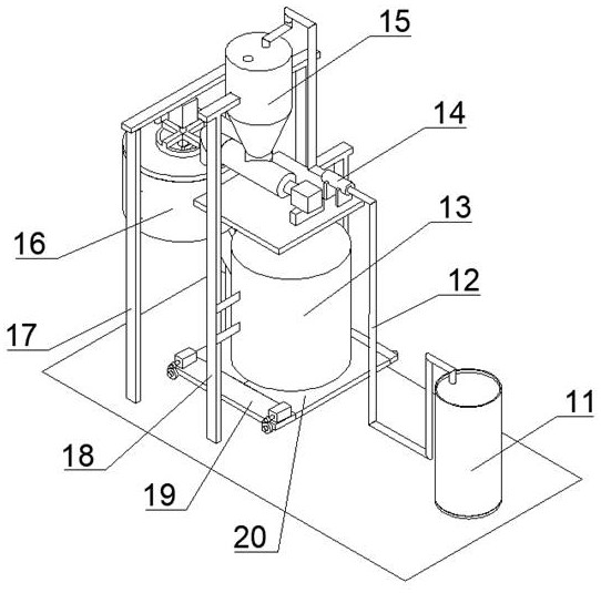
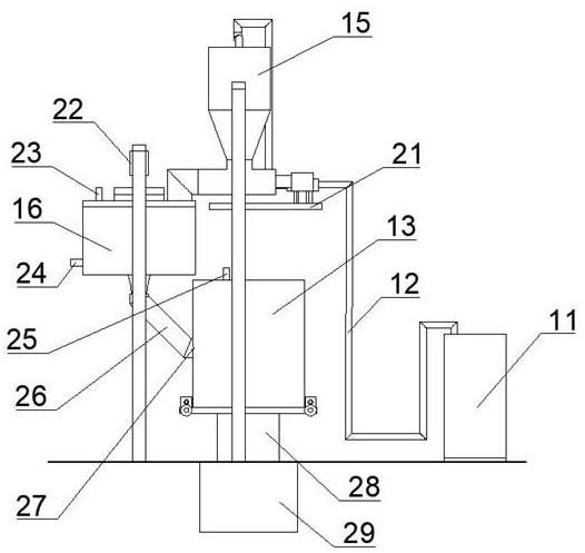
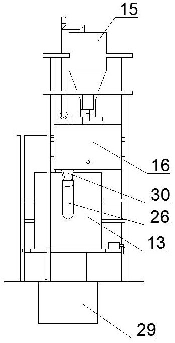
[0036] In order to make the object, technical solution and advantages of the present invention clearer, the present invention will be further described in detail below in conjunction with the accompanying drawings and embodiments. It should be understood that the specific embodiments described here are only used to explain the present invention, and are not intended to limit the present invention, that is, the described embodiments are only some of the embodiments of the present invention, but not all of the embodiments. The components of the embodiments of the invention generally described and illustrated in the figures herein may be arranged and designed in a variety of different configurations.

[0037] Accordingly, the following detailed description of the embodiments of the invention provided in the accompanying drawings is not intended to limit the scope of the claimed invention, but merely represents selected embodiments of the invention. Based on the embodiments of the p...


PUM


Abstract

The invention discloses an efficient sludge drying system for sewage treatment. The efficient sludge drying system comprises a temporary storage tank, a reaction kettle, a centrifugal tank and a forming tank, a tray is arranged at the bottom of the centrifugal tank, the tray is fixedly connected with the centrifugal tank, and a tank cover is detachably mounted at the top of the centrifugal tank; a circle of filter screen is arranged in the centrifugal tank, the filter screen is fixedly connected with the tray, a turntable is arranged in the middle of the filter screen, and the turntable is rotationally connected with the tray; sludge is conveyed to a reaction kettle from a temporary storage tank, a flocculating agent and the like are added, and the sludge enters a centrifugal tank and a forming tank in sequence after a certain time and is subjected to preliminary dehydration and drying forming respectively; wherein a scraping plate is arranged in the centrifugal tank, so that a large amount of sludge can be prevented from being solidified on the inner side of a filter screen, the elongation of the scraping plate is controllable, the position of the scraping plate can be flexibly adjusted according to the sludge dewatering time and the change of the water content, and the optimal dewatering effect can be achieved with the minimum energy consumption.

Description

technical field [0001] The invention belongs to the technical field of sewage treatment, and in particular relates to a high-efficiency sludge drying system for sewage treatment. Background technique [0002] With the development of social economy, the amount of sludge produced in the production process of sewage treatment plants is increasing. The usual treatment square pipe is to transport the sludge to the Burning after secondary drying in thermal power plants. Sludge with 80% water content has a strong odor and putrid smell, which is inconvenient to transport, easily causes environmental pollution, and consumes energy. Moreover, the content of solid impurities in the wastewater generated during the primary drying process is still high, which is not conducive to Subsequent sewage treatment. As a commonly used sludge drying equipment, the filter press is easy to block the feed port of the filter frame, the filter cake is not easy to take out, cannot run continuously, the...

Claims


Application Information

Patent Timeline
Patent Type & Authority Applications(China)
IPC IPC(8): C02F11/127C02F11/13C02F11/14
CPCY02W10/37
Inventor 胡丽黎标李峰孙建江周勤胡静符林
Owner HUNAN ZHONGTUO ENVIRONMENTAL ENG CO LTD
Why Eureka
Try Eureka