
Hydraulic gear-shifting and cooling lubrication system used for hybrid-power transmission

A cooling lubrication and hybrid power technology, applied in gear lubrication/cooling, transmission parts, belts/chains/gears, etc., can solve the problem of large external pressure drop, increased filter load of oil outlet filter, box damage, etc. problems, to achieve the effect of reducing pressure and cavity requirements, alleviating oil pressure fluctuations, and saving layout space

Pending Publication Date: 2019-10-11
无锡明恒混合动力技术有限公司
View PDF0 Cites 6 Cited by
  • Summary
  • Abstract
  • Description
  • Claims
  • Application Information

AI Technical Summary

Problems solved by technology

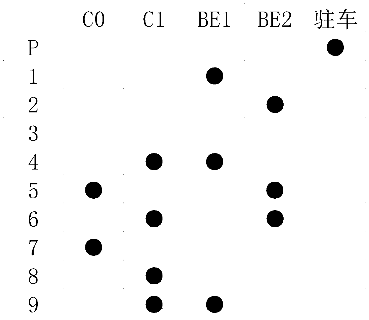
[0004] There are many defects in the E-CVT hybrid transmission in the prior art: for example, the motor, clutch, bearing, planetary row, etc. of the E-CVT hybrid transmission need cooling and lubrication. However, the design of the oil supply system in the prior art is not reasonable enough. In the low temperature environment, the external pressure drop is large, too much cooling oil passes through the external circulation, and the oil temperature rises slowly; The oil pump of the main oil circuit and the oil pump of the main oil circuit will rush to oil when they are working, which increases the filter load of the oil outlet filter; for example, the mechanical structure of the E-CVT hybrid transmission does not allow the clutch and the multi-mode brake at the same time. Closed, but when the car has an electrical failure, the clutch and multi-brake brake of the hydraulic shifting system of the prior art will be closed at the same time, resulting in damage to the box

Method used


Image

  • Hydraulic gear-shifting and cooling lubrication system used for hybrid-power transmission
  • Hydraulic gear-shifting and cooling lubrication system used for hybrid-power transmission

Examples


Embodiment Construction

[0029] The specific implementation of the present invention will be described in detail below in conjunction with the accompanying drawings, so that the advantages and features of the present invention can be more easily understood by those skilled in the art, so as to define the protection scope of the present invention more clearly and accurately.

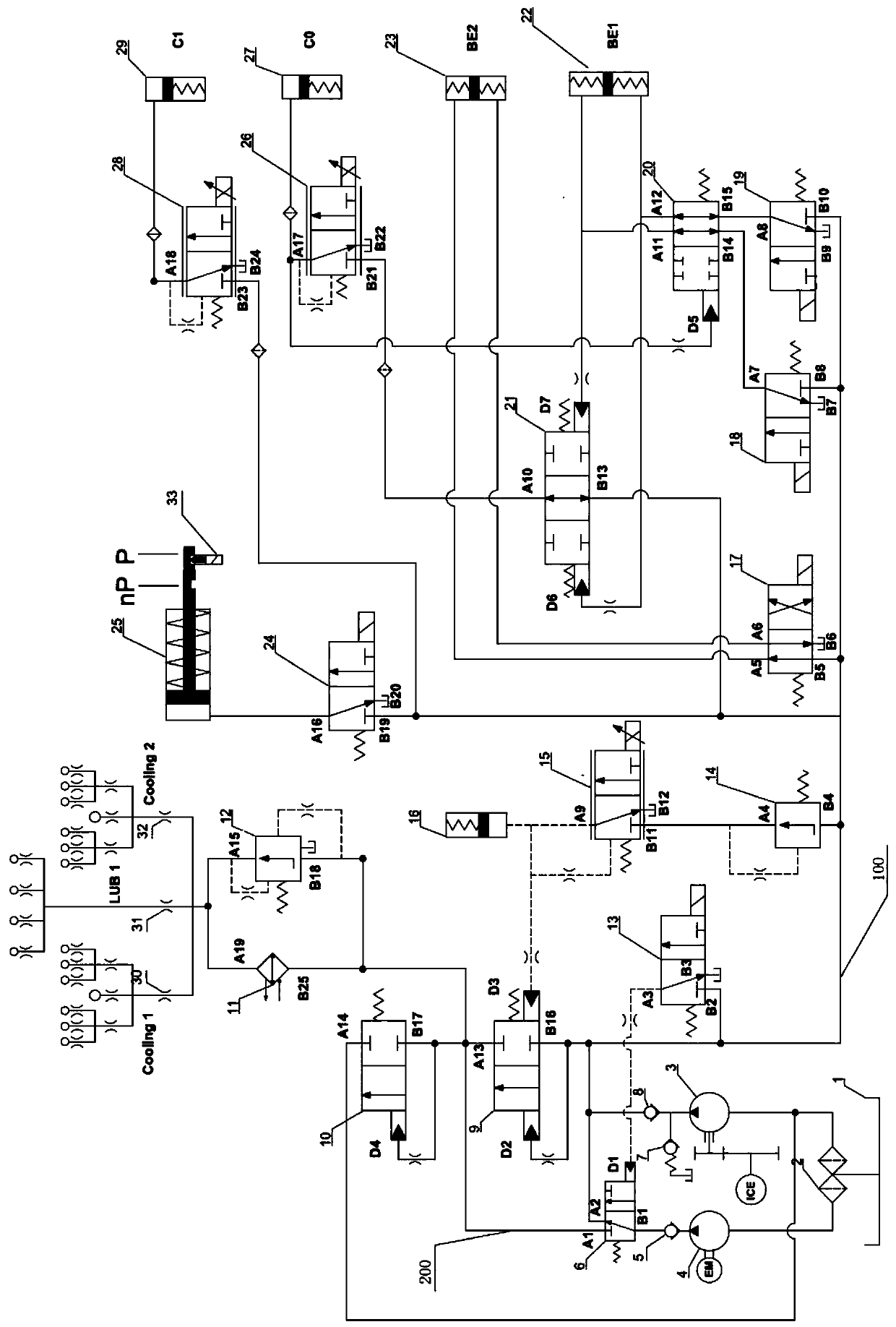
[0030] Such as figure 1 As shown, a hydraulic shifting and cooling lubrication system for a hybrid transmission in this embodiment is characterized in that it includes an oil supply system, a hydraulic shifting system and a cooling lubrication system. The hydraulic gear shifting system includes the main oil circuit, the main oil circuit oil pressure control module and the shift module; the cooling and lubricating system includes a heat dissipation module, an oil circulation control module and an oil distribution module, and the heat dissipation module includes a heat dissipation module Device 11.

[0031] The oil supply system s...


PUM


Abstract

The invention relates to the technical field of hybrid-power transmissions, and discloses a hydraulic gear-shifting and cooling lubrication system used for a hybrid-power transmission. An oil supply system comprises an integrated double-oil-outlet filter screen, a mechanical pump, an electronic pump and a first small-flow switch electromagnetic valve, wherein the mechanical pump communicates witha main oil circuit, oil of the electronic pump can be controlled to communicate with the main oil circuit or a cooling lubrication oil circuit through an oil pump switching valve, and thus, controllable high-pressure and low-pressure separation is achieved. A hydraulic gear-shifting system comprises the main oil circuit, a main oil circuit pressure-control module and a gear-shifting module, and the gear-shifting module is provided with a redundant reversing valve, so that the gear-shifting safety and reliability are improved. A cooling lubrication system comprises a cooling module, an oil major-minor cycle control module and an oil distribution module, so that the oil temperature is well controlled, and cooling lubrication oil is distributed more accurately. Compared with the prior art, the hydraulic gear-shifting and cooling lubrication system is more suitable for a diesel E-CVT hybrid-power transmission, the phenomenon of oil scrambling of two oil pumps is avoided, and the safety andreliability are better guaranteed when an electrical fault occurs.

Description

technical field [0001] The invention relates to the technical field of automatic transmissions, in particular to a hydraulic gear shifting and cooling lubricating system for a diesel power split hybrid transmission (E-CVT). Background technique [0002] With the increasingly stringent national regulations on vehicle fuel consumption and emissions, light commercial vehicles are facing a severe situation. At present, according to the working characteristics of the diesel engine, the development of a hybrid transmission suitable for the diesel engine can maximize the fuel consumption and emissions of the power system. The E-CVT hybrid transmission is a planetary gear set power splitting device, which is different from the traditional CVT continuously variable transmission. The hybrid transmission adopts the E-CVT architecture, which can improve driving comfort. [0003] The E-CVT hybrid transmission requires a hydraulic shifting system to realize automatic shifting of the veh...

Claims


Application Information

Patent Timeline
IPC IPC(8): F16H57/04
CPCF16H57/0415F16H57/0436F16H57/0441F16H57/0404
Inventor 李博杨波洪波昌何正模
Owner 无锡明恒混合动力技术有限公司
Learn More