A flow and pressure control device for a hydraulic press

A pressure control and hydraulic press technology, applied in the field of hydraulic presses, can solve the problems of increasing cost and failure rate, energy loss, low transmission efficiency, etc., and achieve the effects of low manufacturing cost, simple structure and stable pressure

Active Publication Date: 2022-05-24
山东森特克液压有限公司
View PDF0 Cites 0 Cited by
  • Summary
  • Abstract
  • Description
  • Claims
  • Application Information

AI Technical Summary

Problems solved by technology

During the working process of the hydraulic machine, it is generally divided into three processes: the main cylinder idle fast forward, the main cylinder slow work forward and the pressure holding process. The speed and pressure of the hydraulic machine are controlled by the control of the hydraulic components. The current hydraulic machine mainly has the following problems: the hydraulic control system is complex, which increases the cost and failure rate; the structure is complex, the energy loss is serious, and the transmission efficiency is low.

Method used


Image

  • A flow and pressure control device for a hydraulic press
  • A flow and pressure control device for a hydraulic press
  • A flow and pressure control device for a hydraulic press

Examples


Embodiment Construction

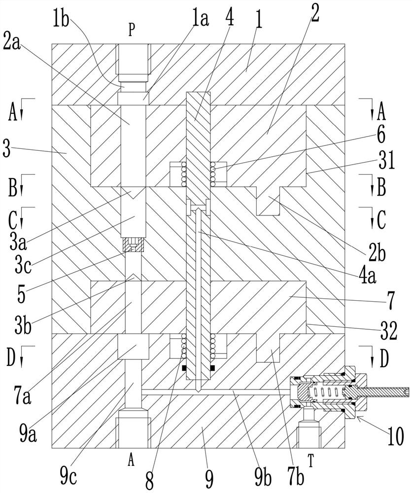
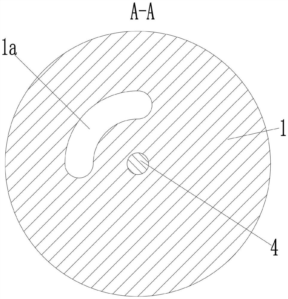
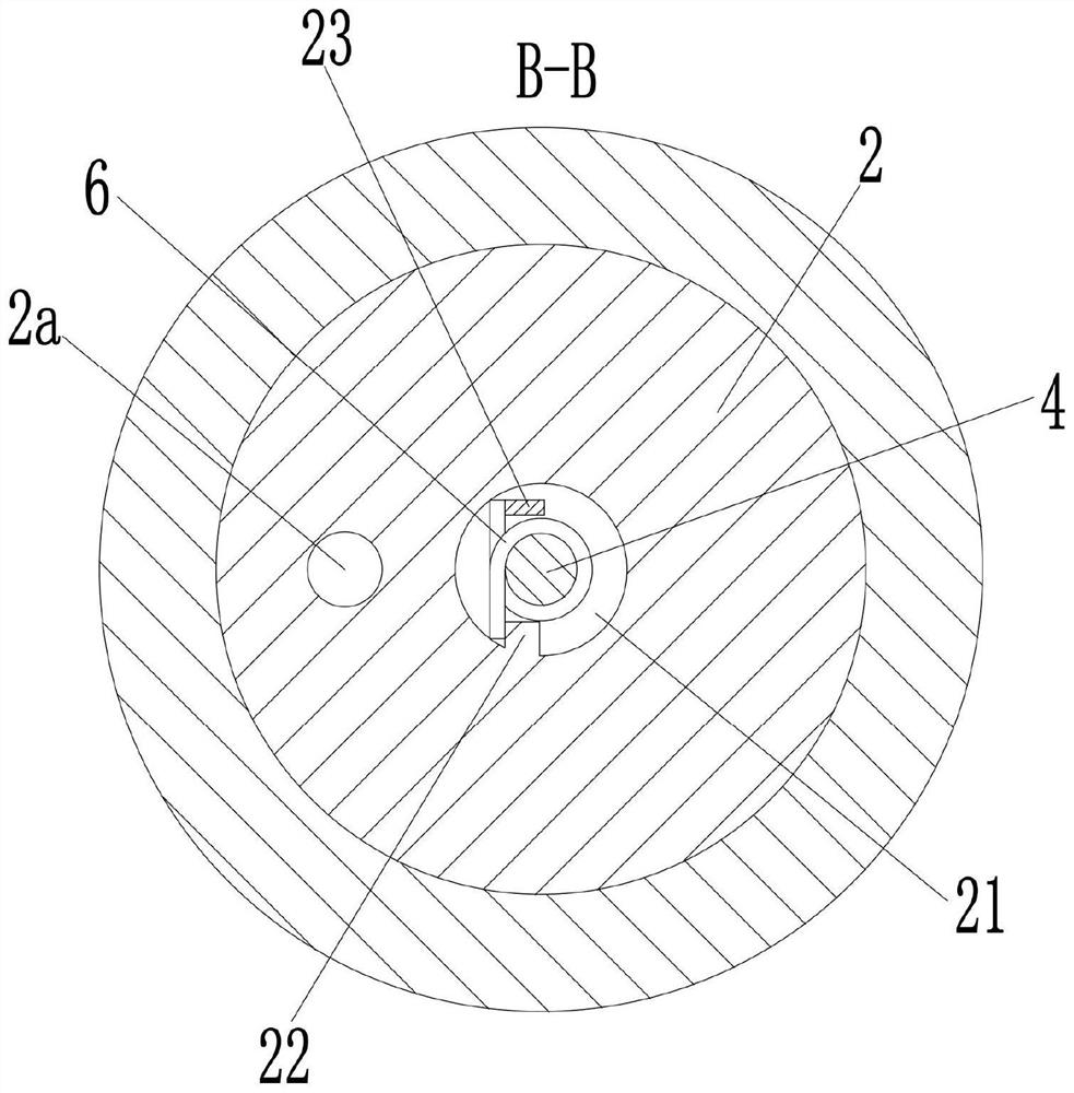
[0024] see Figure 1-6 As shown in the figure, a flow and pressure control device for a hydraulic machine includes a valve body 3, the upper end of the valve body 3 is provided with an upper rotation groove 31, and the lower end is provided with a lower rotation groove 32; An upper end cover 1 is fixedly installed on the upper end, and a lower end cover 9 is fixedly installed at the lower end of the lower turning groove 32; the upper end cover 1 is provided with a P port connected to the outlet of the hydraulic pump, and the lower end cover 9 is provided with a master cylinder. The A port that is connected to the inlet of the reversing valve, and the T port that communicates with the oil tank; the valve body 3 is provided with a shaft 4 between the upper end cover 1 and the lower end cover 9, and the shaft 4 is located in the upper turning groove 31. and the center position of the lower rotation groove 32; the upper rotation groove 31 is rotatably connected with the first valv...


PUM


Abstract

The invention discloses a flow and pressure control device of a hydraulic machine, which comprises a valve body, the upper end of the valve body is provided with an upward rotation groove, and the lower end is provided with a downward rotation groove; the upper end of the valve body is fixedly installed with an upper end Cover, a lower end cover is fixedly installed at the lower end of the lower turning slot; a P port is provided in the upper end cover, and an A port and a T port are arranged in the lower end cover; a shaft rod is arranged in the valve body; the upper turning slot The first spool is rotatably connected to the inside, and the second spool is rotatably connected to the lower trough; a first through hole is provided in the first spool, and an upper dovetail groove is provided at the bottom of the upper trough. The top of the lower turning groove is provided with a lower dovetail groove, the valve body is provided with a second through hole; the second through hole is provided with a screw plug, and the screw plug is provided with a throttling hole; the second through hole is provided with a throttling hole; A third through hole is provided in the second spool; a relief valve assembly is fixedly installed on the side of the lower end cover; the hydraulic flow and pressure control device is not only simple in structure, but also compact in size and low in manufacturing cost.

Description

technical field [0001] The invention belongs to the technical field of hydraulic machines, and in particular relates to a flow and pressure control device of a hydraulic machine. Background technique [0002] Hydraulic press is an important molding equipment. The hydraulic pump is driven by an electric motor to generate high-pressure liquid, and the hydraulic cylinder generates linear motion for work. Due to the wide adaptability of hydraulic machining, it is widely used in metal and non-metal forming and processing occasions. During the working process of the hydraulic press, it is generally divided into three processes: the master cylinder idling fast-forward, the master cylinder slow-speed working and pressure holding. The speed and pressure of the hydraulic press are controlled by the control of the hydraulic components. The current hydraulic press mainly has the following problems: the hydraulic control system is complex, which increases the cost and failure rate; the s...

Claims


Application Information

Patent Timeline
Patent Type & Authority Patents(China)
IPC IPC(8): B30B15/16B30B15/22
CPCB30B15/16B30B15/161B30B15/22
Inventor 吴虹许长鑫亓丽红
Owner 山东森特克液压有限公司
Why Eureka
Try Eureka