
Concrete flaw detection device and flaw detector

A flaw detection device and concrete technology, applied in the field of nuclear technology, can solve the problems of immature reinforced concrete, neutron shielding and imperfect detection schemes, etc., and achieve the effect of improving detection efficiency

Active Publication Date: 2019-10-11
UNIV OF SCI & TECH OF CHINA
View PDF9 Cites 0 Cited by
  • Summary
  • Abstract
  • Description
  • Claims
  • Application Information

AI Technical Summary

Problems solved by technology

[0003] At present, the technology of using neutron backscattering method for reinforced concrete is still immature, and the shielding and detection schemes for generating neutrons are not perfect. The concrete flaw detection device proposed in this patent has studied these aspects and proposed a solution

Method used


Image

  • Concrete flaw detection device and flaw detector
  • Concrete flaw detection device and flaw detector
  • Concrete flaw detection device and flaw detector

Examples


Embodiment 1

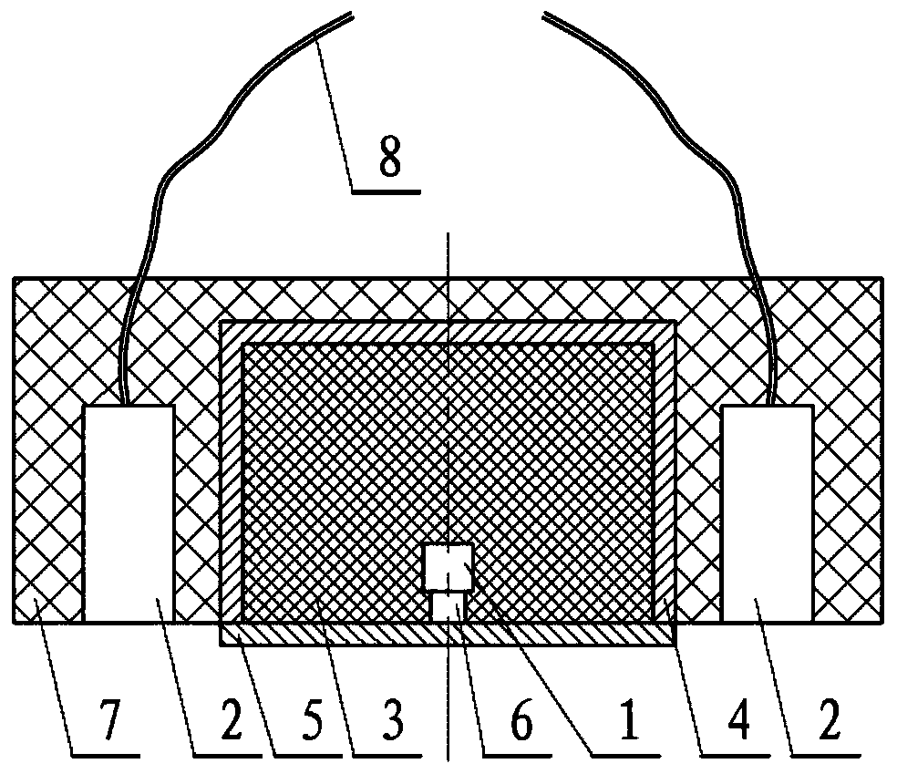
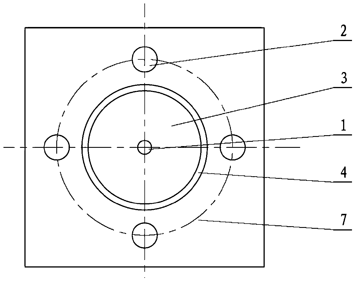
[0031] Such as figure 1 and figure 2 As shown, a concrete flaw detection device is installed on a flaw detector as a probe, and is suitable for flaw detection of a concrete structure covered with a steel plate of a certain thickness, including a neutron source 1, four detectors 2 and a shielding body 3; The neutron source 1 is set at the center of the shielding body 3, surrounded by the shielding body 3, and four detectors 2 are equally spaced outside the shielding body 3 along the circumferential direction of the center of the neutron source 1. Specifically, they can all be installed in a base body 7, and the base body 7 can be a housing of a probe or the like. The flaw detector also includes some lines 8 and data acquisition interfaces, etc., to transmit the data to the computer, and then analyze it through software, which all belong to the known technology and will not be described in detail. The protection scope of this embodiment lies in the concrete flaw detection devi...

Embodiment 2

[0046] A flaw detector includes the concrete flaw detector described in the first embodiment.

[0047] The working process of the flaw detector is: place the concrete flaw detection device of the flaw detector on the surface of the detected object (concrete), start flaw detection, and the computer counts the neutrons detected by the four detectors within a period of time, and finally statistically analyzes the results , according to the detector count and the response map of the cavity depth and position, it can be analyzed whether there is a defect in the detected object. This neutron backscatter flaw detection instrument is suitable for flaw detection of concrete structures covered with steel plates of a certain thickness.

[0048] Such as Figure 4As shown, the initial shield design with a radius thickness of 15cm and a B4C mass content of 0.1 can make the proportion of backscattered particles reach 20%, which makes the detector readings of neutron backscattering flaw dete...


PUM

PropertyMeasurementUnit
radiusaaaaaaaaaa
heightaaaaaaaaaa
thicknessaaaaaaaaaa

Abstract

The invention discloses a concrete flaw detection device. The concrete flaw detection device comprises a neutron source (1), four detectors (2) and a shielding body (3); the neutron source (1) is arranged in the centre of the shielding body (3); four sides are coated by the shielding body (3); the four detectors (2) are arranged outside the shielding body (3) at equal intervals circumferentially and uniformly along the centre of the neutron source (1); the semi-diameter of the shielding body (3) is 15-20 cm; the height is 10-15 cm; the distance between the front of the neutron source (1) and the front detection surface of the shielding body (3) is 1-2 cm; the material of the shielding body (3) is polyethylene doped with boron carbide; the content of boron carbide is 10-15%; a lead protection layer (4) is coated outside the shielding body (3); the thickness of the lead protection layer (4) is 1-2 cm; and the lead protection layer (4) on the front detection surface of the shielding body(3) is provided with a movable cover (5). The detection efficiency is increased; and information of the depth and the horizontal position of a regional defect in the concrete can be obtained by data analysis on a detection result.

Description

technical field [0001] The invention relates to nuclear technology and the field of non-destructive detection technology, in particular to a concrete flaw detection device and flaw detector for non-destructive flaw detection of reinforced concrete structures by neutron backscattering method. Background technique [0002] Because neutron rays have stronger penetrating power to most metal materials than X, gamma rays, and have strong scattering properties to hydrogen-containing materials. Therefore, neutron rays are used in many aspects: such as inspection of internal defects of materials by neutron radiography, determination of water content in insulation materials, determination of hydrogen content in steel, determination of gaps in steel and determination by neutron analysis residual stress, etc. [0003] At present, the technology of using neutron backscattering method for reinforced concrete is not yet mature, and the shielding and detection schemes for generating neutro...

Claims


Application Information

Patent Timeline
Patent Type & Authority Applications(China)
IPC IPC(8): G01N23/204G01N23/20008
CPCG01N23/20008G01N23/204G01N2223/053G01N2223/106G01N2223/646
Inventor 陈志宋昆
Owner UNIV OF SCI & TECH OF CHINA
Learn More