A riveting machine for sheet metal parts and its operating method

A technology of sheet metal parts and riveting machines, applied in the field of sheet metal riveting machines, can solve the problems of low work efficiency, cumbersome operation steps, and reduced work efficiency, so as to achieve high work efficiency, expand the application range, and ensure the pressure riveting effect of effect

Active Publication Date: 2020-11-10
SHANGHAI CHANGKONG MACHINERY
View PDF6 Cites 0 Cited by
  • Summary
  • Abstract
  • Description
  • Claims
  • Application Information

AI Technical Summary

Problems solved by technology

[0004] (1) The existing riveting head can only perform riveting operation on one sheet metal part at a time. When the sheet metal part needs to be riveted in multiple places, it is necessary to perform multiple operations on the position of the sheet metal part and the riveting head. Multiple adjustments, cumbersome operation steps and low work efficiency;
[0005] (2) When the drive frame drives the riveting head to press the rivet placed at the specified position into the sheet metal part, since there is no support outside the rivet, it is difficult to maintain the vertical position of the rivet during the pressing process, and it is easy to be crooked , so rework is often required, further reducing work efficiency

Method used


Image

  • A riveting machine for sheet metal parts and its operating method
  • A riveting machine for sheet metal parts and its operating method
  • A riveting machine for sheet metal parts and its operating method

Examples


Embodiment Construction

[0032] In order to make the technical means realized by the present invention, creative features, goals and effects easy to understand, the following combination Figure 1 to Figure 4 , to further elaborate the present invention.

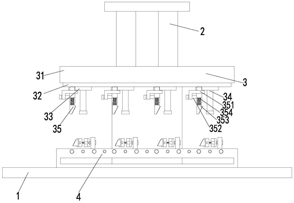
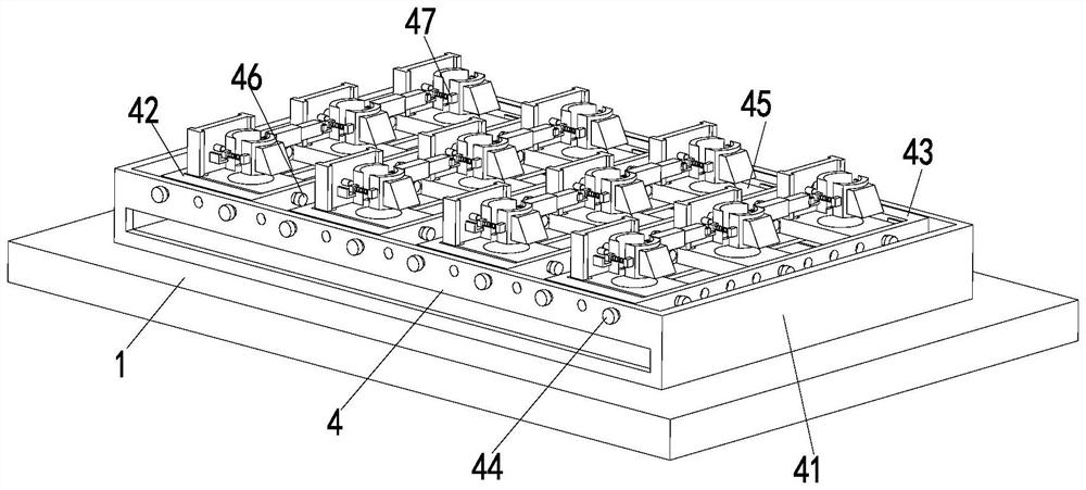
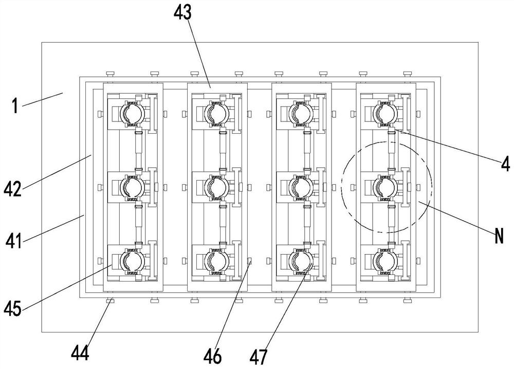
[0033] A riveting machine for sheet metal parts, comprising a workbench 1, a pneumatic frame 2, a riveting mechanism 3 and a guide mechanism 4, the upper end of the workbench 1 is equipped with a pneumatic frame 2, and the pneumatic frame 2 is an up-and-down retractable structure , the lower end of the pneumatic frame 2 is equipped with a riveting mechanism 3, the lower end of the riveting mechanism 3 is arranged with a guiding mechanism 4, and the guiding mechanism 4 is installed on the workbench 1; the structure, principle and control method of the pneumatic frame 2 are all prior art ,in:

[0034]Described riveting mechanism 3 comprises patrix 31, moving plate 32, moving block 33, pressure riveting head 34 and auxiliary frame 35, and patrix 31 is...


PUM


Abstract

The invention relates to a sheet metal part squeeze riveter and an operating method thereof. The sheet metal part squeeze riveter comprises a worktable, a pneumatic rack, a squeeze riveting mechanismand a guiding mechanism. The pneumatic rack is mounted at the upper end of the worktable, the pneumatic rack is of an up-down telescopic structure, the squeeze riveting mechanism is mounted at the lower end of the pneumatic rack, the guiding mechanism is arranged at the lower end of the squeeze riveting mechanism, the guiding mechanism is mounted on the worktable, the squeeze riveting mechanism comprises an upper die, a moving plate, a moving block, a squeeze riveting head and an auxiliary rack, the guiding mechanism comprises a lower die, a shelf, an adjusting plate, a fixed bar, an adjustingblock, a positioning bar and a guiding branch chain, and the auxiliary rack comprises a mounting rack, an adjusting screw, an auxiliary plate and an auxiliary spring. In the squeeze riveting process,a rivet is guided and centralized by means of the guiding mechanism, so that the squeeze riveting position is accurate. The guiding mechanism and the squeeze riveting mechanism are adjusted in position correspondingly according to different to-be-squeeze riveted positions on a metal sheet part, so that the application range is expanded. A plurality of positions can be squeeze riveted simultaneously, so that the work efficiency is high.

Description

technical field [0001] The invention relates to the field of metal processing, in particular to a sheet metal riveting machine and an operating method thereof. Background technique [0002] Riveting machine (also known as riveting machine, spin riveting machine, riveting machine, rolling riveting machine, etc.) . It solves the problem that some sheet metal parts cannot be directly placed on the ordinary slope type cast steel machine for pressure riveting after bending. [0003] The riveting machine mainly includes control components, bed, drive frame and riveting head. When performing riveting, the sheet metal parts must be placed on the bed first, and after the position of the sheet metal parts is limited, the rivets are placed on the waiting At the riveting position, the drive frame drives the riveting head to press the rivet tightly on the sheet metal part. In actual work, there are the following problems: [0004] (1) The existing riveting head can only perform rivet...

Claims


Application Information

Patent Timeline
Patent Type & Authority Patents(China)
IPC IPC(8): B21J15/10B21J15/18B21J15/32B21J15/30B21J15/38
CPCB21J15/10B21J15/18B21J15/30B21J15/32B21J15/38
Inventor 崔路飞李成
Owner SHANGHAI CHANGKONG MACHINERY
Why Eureka
Try Eureka