
Fluid guide frame assembly used on transportation tool dust removal device

A technology of frame assembly and dust removal device, which is applied in transportation and packaging, combined devices, railway car body parts, etc. problems, to achieve the effect of saving manpower and material resources, strong self-cleaning ability, stable and reliable performance

Pending Publication Date: 2019-10-15
ZHONGCHE TIANJIN RAIL TRANSIT EQUIP CO LTD
View PDF0 Cites 3 Cited by
  • Summary
  • Abstract
  • Description
  • Claims
  • Application Information

AI Technical Summary

Problems solved by technology

[0007] The blockage of the ventilation device has brought a lot of workload to the EMU. When the high-speed rail EMU returns to the station, it must check and clean the skirt filter, filter cotton, heat sink and other dust-proof and heat-dissipating equipment; it not only consumes a lot of manpower of the railway, Material and financial resources, and reduce the operating efficiency of high-speed rail EMUs
[0008] There are personal and driving safety hazards at the same time: 1) because the above-mentioned operations will be completed within a few hours after zero o'clock, the time is tight, the workload is large, the working environment is poor, and overlapping operations are required. Many departments cooperate, and there are many operating personnel. Big personal safety hazard
2) Due to the frequent disassembly of the locking device, the phenomenon of poor function of the locking device occurs from time to time, which constitutes a driving safety hazard
[0013] For this reason, the present invention provides a guide body frame assembly used on the dust removal device of the transportation tool, which solves the problem of air intake difficulty of the existing dust removal device and realizes the problem of good heat dissipation of the electrical equipment in the equipment cabin

Method used


Image

  • Fluid guide frame assembly used on transportation tool dust removal device
  • Fluid guide frame assembly used on transportation tool dust removal device
  • Fluid guide frame assembly used on transportation tool dust removal device

Examples


Embodiment Construction

[0078] In order to make the object, technical solution and advantages of the present invention more clear, the present invention will be further described in detail below in conjunction with the examples. It should be understood that the specific embodiments described here are only used to explain the present invention, not to limit the present invention.

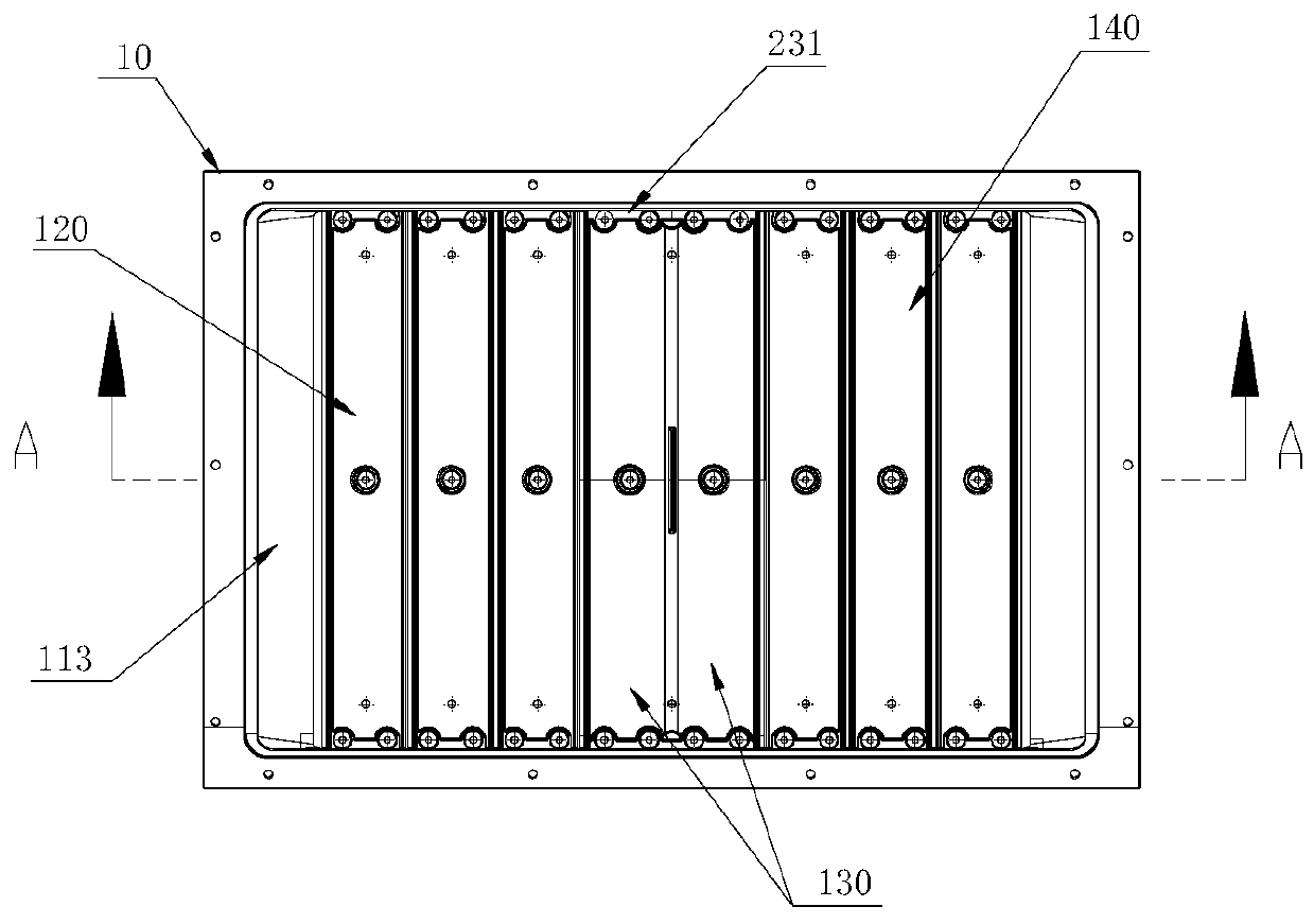
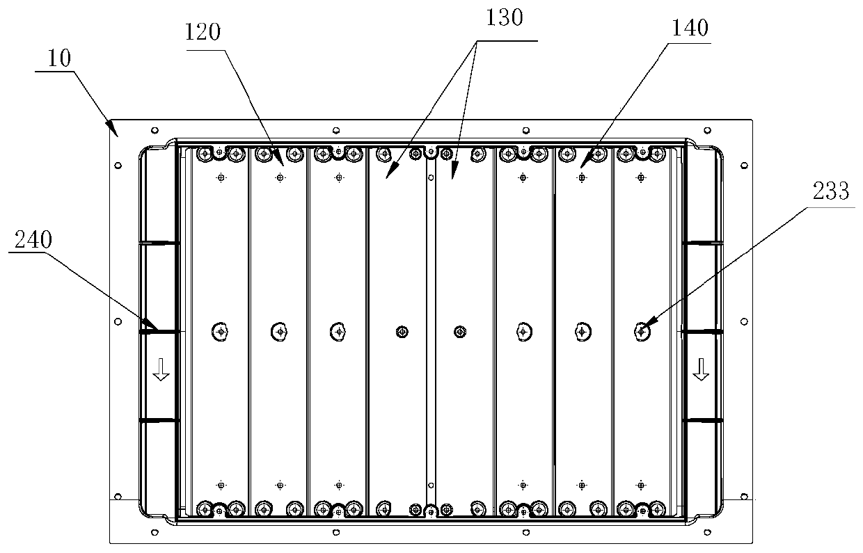
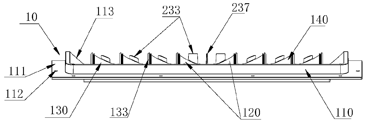
[0079] In order to further illustrate the advantages and technical features of the present invention, the following will be described in detail in conjunction with the relevant drawings. For details, please refer to Figure 1 to Figure 11 :

[0080] A guide body frame assembly used on a dust removal device of a transportation tool, including a guide body frame assembly 10; the guide body frame assembly 10 includes an inner frame 110, which is arranged around the inner frame and integrally connected with the inner frame The mounting plate 111 is provided with a mounting hole 112 connected to the air inlet of the equipment c...


PUM


Abstract

The invention discloses a fluid guide frame assembly used on a transportation tool dust removal device, and belongs to the technical field of dust removal. The fluid guide frame assembly comprises aninner frame and a mounting plate, and a middle lower flow guide plate, an air inlet lower flow guide plate and an air outlet lower flow guide plate are arranged in the inner frame; the middle lower flow guide plate divides the inner frame into two ventilation areas, one ventilation area is an air inlet area, and the other ventilation area is an air outlet area; and a middle upper flow guide plate,an air inlet upper flow guide plate and an air outlet upper flow guide plate are fixedly arranged above the middle lower flow guide plate, the air inlet lower flow guide plate and the air outlet lower flow guide plate correspondingly. According to the fluid guide frame assembly used on the transportation tool dust removal device, when a high-speed motor train unit operates, strong reverse airflowis generated at an air inlet of a skirt plate so that floating objects and the air inlet airflow are separated automatically, and the separated floating objects are discharged and returned to the atmosphere under the wrapping action by airflow of a main ventilation channel; and meanwhile, under the action of the flow guide surfaces of the flow guide plates, the air pressure of a filter screen isincreased, a high-pressure area is formed, and active air supply to an equipment cabin is realized.

Description

technical field [0001] The invention belongs to the technical field of dust removal for transportation tools, in particular to a guide body frame assembly used for dust removal devices for transportation tools. Background technique [0002] In today's society, rail transportation mainly includes diesel locomotives, electric locomotives, EMUs, high-speed rail, passenger and truck carriages, light rails, subways and other transportation carriers, and road transportation mainly includes automobiles. Their normal operation needs to inhale a large amount of air to meet the needs of combustion of internal combustion engines, heat dissipation of electronic and mechanical components, and cooling of air conditioners and other facilities. With the inhalation of a large amount of air, there are a large number of floating objects such as dust, catkins, plant leaves, paper scraps, plastics, etc. in the air, which are adsorbed on the dust-proof devices of various air intakes and gradually...

Claims


Application Information

Patent Timeline
IPC IPC(8): B61D27/00B01D50/00
CPCB61D27/00B61D27/009B01D50/20
Inventor 杨强
Owner ZHONGCHE TIANJIN RAIL TRANSIT EQUIP CO LTD
Learn More