Ultra-high-performance concrete-partial profile steel combined beam unit, ultra-high-performance concrete-profile steel combined beam unit and combined beam

An ultra-high-performance, concrete beam technology, which is applied in bridges, bridge parts, bridge construction, etc., can solve the problem that the durability of bridges cannot meet the design service life, reduce the connection strength of bridge decks at joints, and affect the traffic flow of roads Pedestrian safety and other issues, to achieve the effect of simple structure, firm and reliable connection, and enhanced structural strength

Pending Publication Date: 2019-10-15
HUNAN UNIV
View PDF0 Cites 4 Cited by
  • Summary
  • Abstract
  • Description
  • Claims
  • Application Information

AI Technical Summary

Problems solved by technology

[0003] At present, a lot of technical research has been done on the structural mechanical properties and design methods of several types of novel composite beams, but the solution to the joint connection problem of the prefabricated ultra-high-performance concrete-partial steel composite beams at the construction site is not the same as No, it is an important link related to whether it can be implemented in actual engineering applications. It will not only directly affect the bearing capacity and service life of the bridge, but also affect the smoothness of the road and the safety of drivers and pedestrians.
At the joints, the bridge deck, which should be connected by the regularly distributed steel fibers contained in the ultra-high performance concrete composite beams, is "truncated", which greatly reduces the connection strength at the joints and the continuity of the bridge deck, resulting in Under the action of stress, local damage or cracks are prone to appear at the joints, making it difficult for the durability of the bridge to meet the requirements of the design service life
[0004] Due to their novel structural combination, the connection of ultra-high performance concrete-partial steel composite beams and ultra-high performance concrete-steel composite beams at the construction site is different from that of general steel-concrete composite beams. Design and study of novel structures at joints

Method used


Image

  • Ultra-high-performance concrete-partial profile steel combined beam unit, ultra-high-performance concrete-profile steel combined beam unit and combined beam
  • Ultra-high-performance concrete-partial profile steel combined beam unit, ultra-high-performance concrete-profile steel combined beam unit and combined beam
  • Ultra-high-performance concrete-partial profile steel combined beam unit, ultra-high-performance concrete-profile steel combined beam unit and combined beam

Examples


Embodiment 1

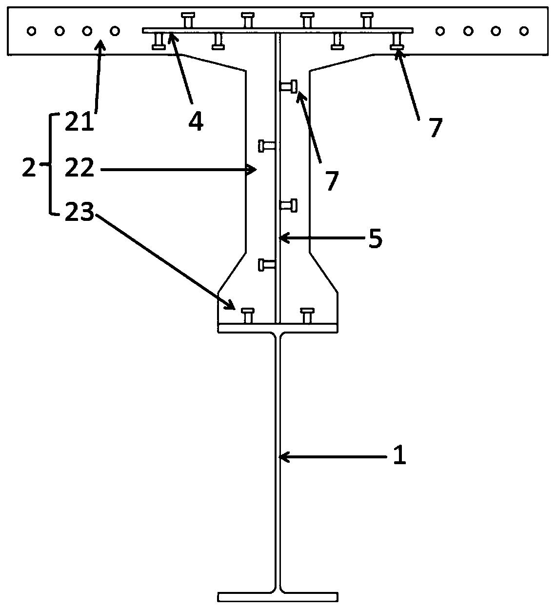
[0061] Such as Figure 1-Figure 5 , Figure 18 As shown, the ultra-high performance concrete-partial steel composite beam unit of this embodiment, the ultra-high performance concrete-partial steel composite beam unit includes a main beam steel 1 and an ultra-high performance concrete beam 2 fixed on the main beam steel 1, The ultra-high-performance concrete beam 2 includes a top plate 21, a web 22 and a bottom plate 23. The end of the top plate 21 is provided with a half-notch 3, and the half-notch 3 is provided with a top-plate reinforcing steel plate 4 arranged in the longitudinal bridge direction. The top-plate reinforcing steel plate 4 One end is fixed in the top plate 21, and the other end extends out of the end of the top plate 21. The web 22 is provided with a web strengthening steel plate 5 arranged in the longitudinal bridge direction, and one end of the web strengthening steel plate 5 is fixed in the web 22. , and the other end extends from the end of the web 22 . ...

Embodiment 2

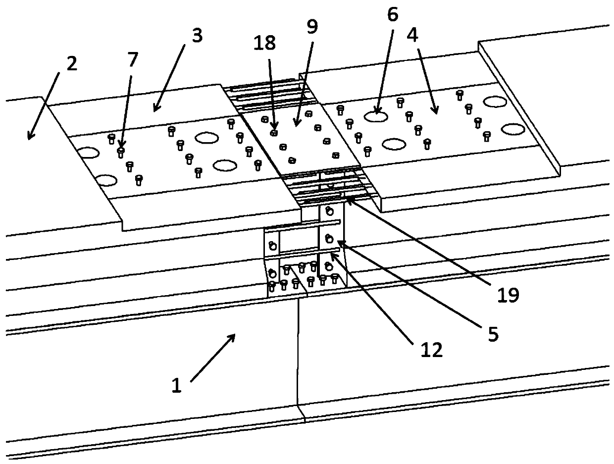
[0073] Such as Figure 6-8 , Figure 18 As shown, the ultra-high performance concrete-partial steel composite beam unit of this embodiment, the ultra-high performance concrete-partial steel composite beam unit includes a main beam steel 1 and an ultra-high performance concrete beam 2 fixed on the main beam steel 1, The ultra-high-performance concrete beam 2 includes a top plate 21, a web 22 and a bottom plate 23. The end of the top plate 21 is provided with a half-notch 3, and the half-notch 3 is provided with a top-plate reinforcing steel plate 4 arranged in the longitudinal bridge direction. The top-plate reinforcing steel plate 4 One end is fixed in the top plate 21, and the other end extends out of the end of the top plate 21. The web 22 is provided with a web strengthening steel plate 5 arranged in the longitudinal bridge direction, and one end of the web strengthening steel plate 5 is fixed in the web 22. , and the other end extends from the end of the web 22 . The lon...

Embodiment 3

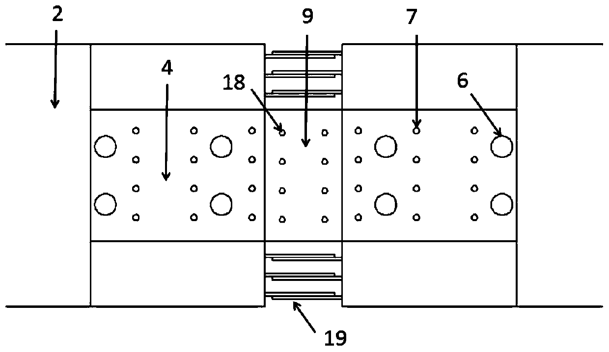
[0086] Such as Figure 9-11 , Figure 18 As shown, the ultra-high performance concrete-partial steel composite beam unit of this embodiment, the ultra-high performance concrete-partial steel composite beam unit includes a main beam steel 1 and an ultra-high performance concrete beam 2 fixed on the main beam steel 1, The ultra-high-performance concrete beam 2 includes a top plate 21, a web 22 and a bottom plate 23. The end of the top plate 21 is provided with a half-notch 3, and the half-notch 3 is provided with a top-plate reinforcing steel plate 4 arranged in the longitudinal bridge direction. The top-plate reinforcing steel plate 4 One end is fixed in the top plate 21, and the other end extends out of the end of the top plate 21. The web 22 is provided with a web strengthening steel plate 5 arranged in the longitudinal bridge direction, and one end of the web strengthening steel plate 5 is fixed in the web 22. , and the other end extends from the end of the web 22 . The lo...


PUM


Abstract

The invention discloses an ultra-high-performance concrete-partial profile steel combined beam unit. An ultra-high-performance concrete beam comprises a top plate, a web and a bottom plate, half notches are formed in the ends of the top plate, a top plate reinforcing steel plate which is arranged in the longitudinal direction of a bridge is arranged at each of the half notches, one ends of the topplate reinforcing steel plates are fixedly arranged in the top plate, and the other ends of the top plate reinforcing steel plates extend out of the end of the top plate, a web reinforcing steel plate which is arranged in the longitudinal direction of the bridge is arranged in the web, one end of the web reinforcing steel plate is fixedly arranged in the web, and the other end of the web reinforcing steel plate extends out of the end of the web. The invention further provides an ultra-high-performance concrete-profile steel combined beam unit. The invention further provides a combined beam formed by connecting the two beam units. By means of the ultra-high-performance concrete-partial profile steel combined beam unit or the ultra-high-performance concrete-profile steel combined beam unit,the connection structure at the joint of the adjacent beam units is simple and reasonable, and the stress performance is excellent.

Description

technical field [0001] The invention belongs to the field of bridge structures, in particular to a composite beam unit and a composite beam. Background technique [0002] Ultra-high performance concrete (UHPC) is an ultra-high-performance fiber-reinforced cement-based composite material with high compressive strength, high tensile strength, high modulus, high ductility, and high durability. It is composed of cement, mineral admixtures, quartz Sand, quartz powder, steel fiber, water reducing agent and water are configured according to the theory of maximum density, which minimizes the defects inside the material. Due to the high strength and large elastic modulus of ultra-high performance concrete, existing engineering experience shows that ultra-high performance concrete can effectively reduce the weight of the structure and improve the utilization efficiency of the structure. [0003] At present, a lot of technical research has been done on the structural mechanical proper...

Claims


Application Information

Patent Timeline
Patent Type & Authority Applications(China)
IPC IPC(8): E01D2/00E01D19/00
CPCE01D2/00E01D19/00
Inventor 邵旭东刘琼邱明红李玉祺赵旭东
Owner HUNAN UNIV
Why Eureka
Try Eureka