Oxygen supply device of high-temperature pyrolysis gasification furnace

An oxygen supply device and high-temperature pyrolysis technology, applied in incinerators, indirect carbon dioxide emission reduction, non-flammable liquid/gas transportation, etc., can solve the problems of no blocking device and blockage at the oxygen supply port, and achieve the reduction of flue gas, Effects of cost reduction and sufficient waste incineration

Pending Publication Date: 2019-10-15
GUANGXI HONGSHENGYUAN ENVIRONMENTAL PROTECTION CO LTD
View PDF1 Cites 0 Cited by
  • Summary
  • Abstract
  • Description
  • Claims
  • Application Information

AI Technical Summary

Problems solved by technology

[0004] In the above-mentioned prior art, the oxygen supply port is not equipped with a blocking device, which is easy to cause blockage

Method used


Image

  • Oxygen supply device of high-temperature pyrolysis gasification furnace
  • Oxygen supply device of high-temperature pyrolysis gasification furnace
  • Oxygen supply device of high-temperature pyrolysis gasification furnace

Examples


Embodiment 1

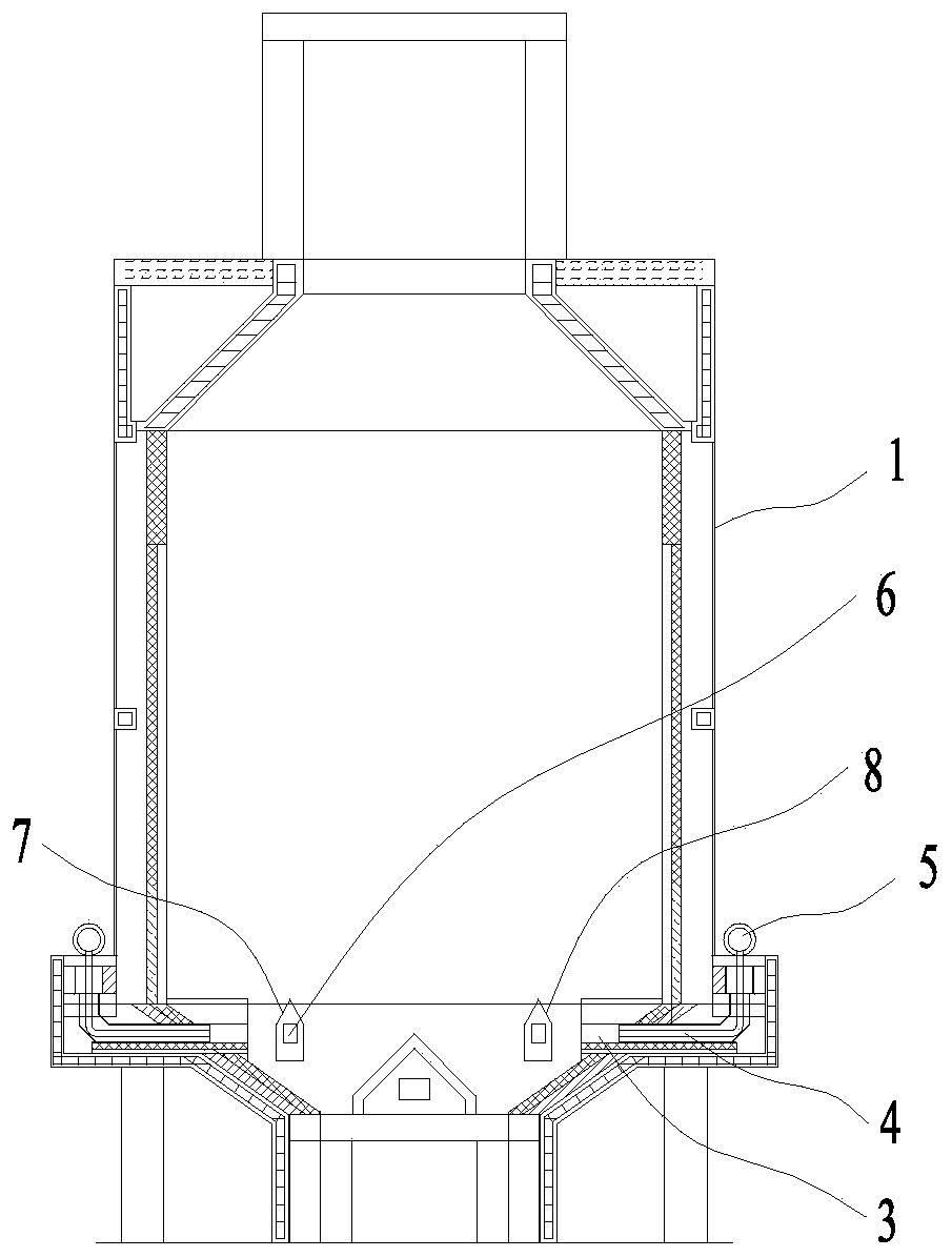
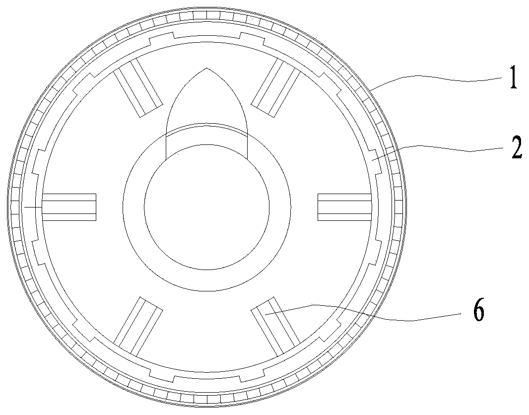
[0022] See also figure 1 with figure 2 , The embodiment of the present invention provides an oxygen supply device for a high-temperature cracking gasifier, which is installed in the cracking furnace 1, and includes an air duct 2 arranged on the inner wall of the cracking furnace 1, and the air duct 2 is provided with an inlet toward the side of the inner wall of the cracking furnace 1. The tuyere 3 and the air inlet 3 are connected to the outside of the cracking furnace 1 through the air inlet pipe 4. A fan 5 is provided on the air inlet pipe 4. The side of the air duct 2 facing away from the air inlet 3 is provided with an air outlet 6, and a shielding device 7 is provided above the air outlet 6.

[0023] When the oxygen supply device of the high-temperature pyrolysis gasifier of the present invention is in use, the fan 5 introduces fresh air into the air inlet pipe 4, and then into the air duct 2 from the air inlet 3, and finally through the air outlet 6 of the air duct 2 Oxy...

Embodiment 2

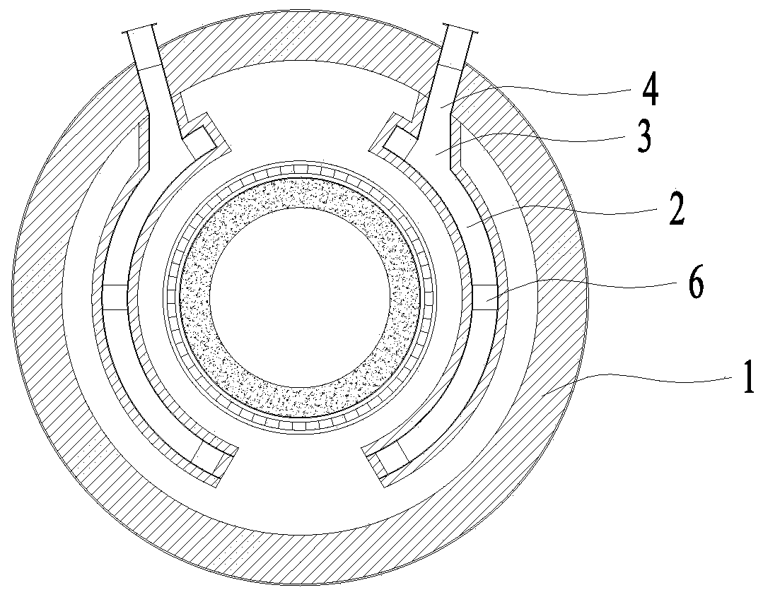
[0028] See image 3 In this embodiment, except that the structure of the air duct 2 is different, everything else is the same as the embodiment 1.

[0029] In this embodiment, two air ducts 2 are provided, and each air duct 2 is arc-shaped. Each air duct 2 is provided with an air inlet 3 on the side facing the inner wall of the cracking furnace 1, and the air inlet 3 is connected to the outside of the cracking furnace 1 through an air inlet pipe 4. A fan 5 is provided on the air inlet pipe 4. Three air outlets 6 are evenly provided on the side of each air duct 2 facing away from the air inlet 3.

[0030] When in use, the fan 5 introduces fresh air into the air inlet pipe 4, and then enters the air duct 2 from the air inlet 3, and finally supplies oxygen to the cracking furnace 1 through the air outlet 6 of the air duct 2, so that the material is in the cracking furnace Fully burn within 1

Embodiment 3

[0032] See Figure 4 In this embodiment, except that the structure of the shielding device 7 is different, everything else is the same as the first embodiment.

[0033] In this embodiment, the shielding device 7 is an arc-shaped baffle 9, and the arc-shaped baffle 9 protrudes upward. When the rubbish falls down, it continues to slide down along the arc edge of the curved baffle 9, thereby avoiding the rubbish blocking the air outlet 6.


PUM


Abstract

The invention discloses an oxygen supply device of a high-temperature pyrolysis gasification furnace. The oxygen supply device is arranged on the pyrolysis furnace and comprises an air duct arranged on the inner wall of the pyrolysis furnace, wherein an air inlet is formed in one side, facing the inner wall of the pyrolysis furnace, of the air duct; the air inlet communicates with the outside of the pyrolysis furnace through an air inlet pipeline; a fan is arranged on the air inlet pipeline; an air outlet is formed in one side, back to the air inlet, of the air duct; and a shielding device isarranged above the air outlet. According to the oxygen supply device, sufficient oxygen can be supplied to combust materials completely without a combustion improver, flue gas is reduced, and cost isreduced accordingly; and the shielding device is arranged at the air outlet but does not block the air outlet, and therefore oxygen can be continuously supplied to burn the garbage fully.

Description

Technical field [0001] The invention relates to the technical field of oxygen supply for a cracking furnace, in particular to an oxygen supply device for a high-temperature cracking gasifier. Background technique [0002] The existing oxygen supply system has insufficient oxygen supply and incomplete combustion of materials, which produces toxic and harmful substances and brings secondary pollution to the environment. [0003] Chinese patent CN201221777Y discloses an oxygen supply device for biomass gasifier, which is composed of an air inlet pipe and an oxygen supply ring. The oxygen supply ring is a ring structure, and the ring is provided with two multi-point oxygen supply ports. The oxygen supply ports are spaced apart, and the angle formed by the connection between the inner and outer oxygen supply ports and the center of the circle is between 10 and 45 degrees. One end of the air inlet pipe is connected with a fan and one end is connected with an oxygen supply ring. The stru...

Claims


Application Information

Patent Timeline
Patent Type & Authority Applications(China)
IPC IPC(8): F23G5/027F23G5/44F23L7/00
CPCF23G5/0276F23G5/44F23L7/007Y02E20/34
Inventor 黄敏白洋冯光兴熊明飞向瑞群李月丹韦永烈谢鹏李伟凌子琨
Owner GUANGXI HONGSHENGYUAN ENVIRONMENTAL PROTECTION CO LTD
Why Eureka
Try Eureka