Pneumatic revolving door device and method for self-starting test outlet of shock tunnel air inlet channel

A shock tunnel and air inlet technology, applied in the field of pneumatic revolving door device at the exit of the shock tunnel inlet self-starting test, can solve the problem of blowing away, difficult to control the quality of the preset block, and the inability to enter the air inlet Self-starting test throttling and other issues, to achieve the effect of reliable test basis

Active Publication Date: 2019-10-15
CHINA AERODYNAMICS RES & DEV CENT
View PDF6 Cites 5 Cited by
  • Summary
  • Abstract
  • Description
  • Claims
  • Application Information

AI Technical Summary

Problems solved by technology

[0009] ① Equipped with power throttling cone technology, the running time of the motor that pushes the throttling cone forward or backward, the running time of the guide rail slider mechanism or the screw nut mechanism is much longer than the test time of the shock wave tunnel, so it cannot be used for shock wave wind Self-starting test throttling of the intake port of the hole
It has been popularized and used in temporary wind tunnels, but it is possible to use it in shock wave wind tunnels after a lot of additional research is required on synchronous control and response speed
[0011] ③Preset lightweight block technology, it is difficult to control the quality of preset block
One is that if the mass is too light, it will easily cause the block to be blown away by the airflow from the intake duct when the flow field in the wind tunnel is not stable, and the throttling effect of the intake duct will not be achieved, so the throttling test will fail; The air flow in the stable flow field of the hole cannot blow away the blockage, causing the inlet port to fail to start and the inlet port throttling test to fail

Method used


Image

  • Pneumatic revolving door device and method for self-starting test outlet of shock tunnel air inlet channel
  • Pneumatic revolving door device and method for self-starting test outlet of shock tunnel air inlet channel
  • Pneumatic revolving door device and method for self-starting test outlet of shock tunnel air inlet channel

Examples


Embodiment 1

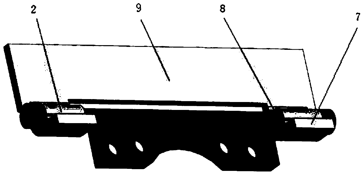
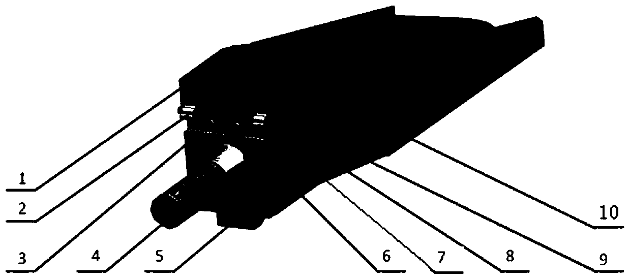
[0033]A pneumatic revolving door device for the self-starting test exit of the inlet of a shock wave wind tunnel, comprising: a door panel 9 located at the end of the inlet outlet, the door panel 9 is rotatably connected to a rotating shaft 8 through a bushing 2, and the rotating shaft 8 is fixed to the inlet of the wind tunnel. Below the outlet end of the air duct, the lower edge of the door panel 9 is vertically connected to the limit step 7. The size of the door panel is larger than the size of the inner flow channel of the air intake duct and smaller than the outer contour size of the outlet end face of the air intake duct, so that the door panel starts at the intake duct. The air inlet is closed before but does not exceed the outer contour of the outlet end face of the air inlet. The limit step 7 limits the rotation of the door panel 9 around the rotating shaft 8 to be no more than 90 degrees. The upper edge of the door panel 9 is close to the outlet end of the air inlet. ...

Embodiment 2

[0037] This embodiment provides a method for using the device in Embodiment 1 to perform high-speed photography of the action history of the pneumatic revolving door at the outlet of the shock tunnel inlet self-starting test. A pneumatic revolving door device is installed at the end of the inlet outlet, and then the The self-starting test of the airway is carried out, and the shadow meter system is used as the projection lighting system of the pneumatic revolving door device. The projection image of the high-speed pneumatic revolving door in the self-starting test of the air inlet is recorded on the camera CCD through a high-speed camera, and then It is transmitted to a computer via a gigabit network for storage analysis.

[0038] Specifically, the light source of the shader system is a 36V400W halogen tungsten lamp, the shooting frame rate of the high-speed camera is 10000fps, the exposure time is 1 / 440000s, and the pixel resolution of the image is 896*848.

Embodiment 3

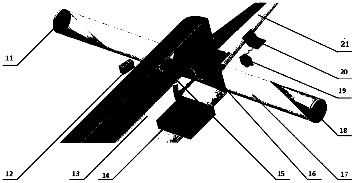
[0040] This embodiment provides a kind of high-speed photographic experiment system in embodiment 1 or embodiment 2, comprises first schlieren reflector 11, tungsten halogen light source 12, wind tunnel test section 13, model support 14, wind tunnel observation window 15. Inlet model assembly 16, parallel light beam 17, second schlieren mirror 18, high-speed camera 19, computer 20, wind tunnel nozzle 21;

[0041] The air inlet model assembly 16 is fixed on the model support 14, the model support 14 is located on the central axis of the wind tunnel test section 13, and the first schlieren reflector 11 and the second schlieren reflector 18 are respectively located at the center axis of the wind tunnel test section 13. At the two ends outside the section, the halogen tungsten light source 12 is located outside the wind tunnel test section 13. The light emitted by the halogen tungsten light source 12 is projected onto the surface of the first schlieren reflector 11, and the paralle...


PUM

PropertyMeasurementUnit
Thicknessaaaaaaaaaa

Abstract

The invention provides a pneumatic revolving door device for a self-starting test outlet of a shock tunnel air inlet channel, a method for performing high-speed photography on the action process of the self-starting test outlet pneumatic revolving door of the shock tunnel air inlet channel by using the device, and a throttling method for performing the self-starting test of the shock tunnel air inlet channel. The device comprises a door plate positioned at the end part of the outlet of the air inlet channel, the door plate is rotatably connected with a rotating shaft through a shaft sleeve, the rotating shaft is fixed below the outlet end part of the air inlet channel, the lower edge of the door plate is vertically connected with a limiting step, the included angle between the inclined door plate and the end surface of the outlet of the air inlet channel is 3-5 degrees, and after the flow field of a wind tunnel is stable, the pneumatic revolving door rotates around the rotating shaft under the pushing of air flow and is opened to start the air inlet channel; and the method can conveniently carry out effective automatic throttling control on the self-starting test of the shock tunnel air inlet channel, and provides reliable test basis for mastering the flow control rule of the air inlet channel and the design of the hypersonic speed air inlet channel.

Description

technical field [0001] The invention belongs to the technical field of experimental aerodynamics, and relates to a pneumatic revolving door device for the self-starting test outlet of the inlet of a shock tunnel, and uses the device to perform the action of the pneumatic revolving door for the self-starting test outlet of the inlet of the shock tunnel The method of high-speed photography, the throttling method of the self-starting test of the shock tunnel inlet. Background technique [0002] The intake port is the first aerodynamic component of the scramjet engine, and its performance will directly affect the working characteristics of the power system. The self-starting and stable operation of the intake port is the prerequisite for the normal operation of the power system. If the intake port does not start, the combustion chamber will not work normally, and the power system will not be able to generate the power it should. Therefore, the self-starting performance is one o...

Claims


Application Information

Patent Timeline
IPC IPC(8): G01M9/04
CPCG01M9/04
Inventor 余安远周凯杨辉贺元元倪鸿礼陈锐杰袁仕果贺佳佳吴杰黎崎胡俊逸
Owner CHINA AERODYNAMICS RES & DEV CENT
Why Eureka
Try Eureka