
Carrier-to-Noise Ratio Calibration Method of High-precision Noise-fixed-Signal Transformation Method

A calibration method and carrier-to-noise ratio technology, applied in noise figure or signal-to-noise ratio measurement, line transmission components, line transmission monitoring/testing, etc., can solve the problems of large error of real carrier-to-noise ratio and influence of engineering applications, etc., to achieve The effect of reducing calibration error, improving quality, and improving engineering design efficiency

Active Publication Date: 2020-09-11
XIDIAN UNIV
View PDF13 Cites 0 Cited by
  • Summary
  • Abstract
  • Description
  • Claims
  • Application Information

AI Technical Summary

Problems solved by technology

This carrier-to-noise ratio calibration method is relatively simple to calculate, but it ignores the influence of the noise figure of the attenuator, combiner, and cable in the combiner system on the noise power spectral density, which makes the expected pure signal power smaller In some cases, the calibrated carrier-to-noise ratio has a large error compared with the real carrier-to-noise ratio of the noisy signal, which has a significant impact on practical engineering applications.

Method used


Image

  • Carrier-to-Noise Ratio Calibration Method of High-precision Noise-fixed-Signal Transformation Method
  • Carrier-to-Noise Ratio Calibration Method of High-precision Noise-fixed-Signal Transformation Method
  • Carrier-to-Noise Ratio Calibration Method of High-precision Noise-fixed-Signal Transformation Method

Examples


Embodiment

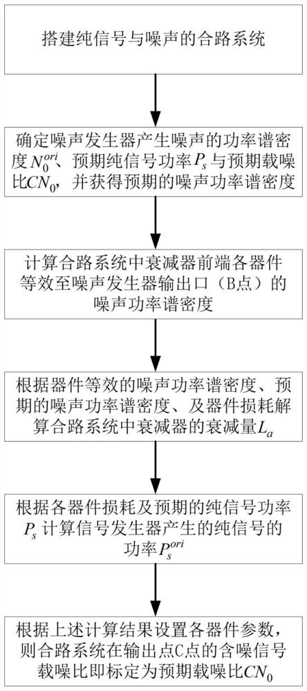
[0042] The carrier-to-noise ratio calibration method of the high-precision noise-fixed-signal conversion method of the present invention, such as figure 1 As shown, follow the steps below:

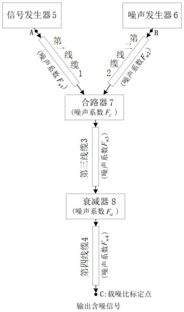
[0043] S1, build a combined system of pure signal and noise, see figure 2 ; The combined system includes a signal generator 5, a noise generator 6, a combiner 7, an attenuator 8, and a coaxial cable, and the output port of the signal generator 5 and the output port of the noise generator 6 pass through the cable respectively Connect with combiner 7, combiner 7 is connected with attenuator 8 through cable; The signal flow in the system is: signal generator 5 produces pure signal (corresponding to figure 2 point A), while the noise generator 6 produces white noise (corresponding to figure 2 point B), the pure signal is input to the combiner 7 through the first cable 1, and the white noise is input to the combiner 7 through the second cable 2, and the noise-containing signal output by th...


PUM


Abstract

The invention discloses a carrier-to-noise ratio calibration method in a high-precision fixed-noise and variable-signal way. The calibration method specifically comprises the following steps: constructing a combining system of pure signal and noise; determining output noise power spectral density as shown in description, expected pure signal power Ps and expected carrier-to-noise ratio CN0 of a noise generator in the combining system; determining the decrement La of an attenuator, and determining the output pure signal power as shown in description of the signal generator according to the total loss and expected pure signal power Ps between a signal generator output port and the combining system carrier-to-noise ratio calibration point, and orderly setting the output pure signal power of the signal generator in the combining system as FORMULA as shown in description and the decrement of the attenuator as La, wherein the output noise power spectral density of the noise generator is sameas a determined value, and the combining system outputs the noise-containing signal carrier-to-noise ratio CN0', namely accomplishing the carrier-to-noise ratio calibration. By considering the influence on the noise power spectral density by the noise coefficients in the attenuator in the combining system, the combiner and the cable, the carrier-to-noise ratio calibration error is greatly reduced, and the precision of the carrier-to-noise ratio calibration in the fixed noise and variable-signal way is improved.

Description

technical field [0001] The invention belongs to the technical fields of electronic information engineering and aerospace engineering, and relates to a carrier-to-noise ratio calibration method in a high-precision noise-fixed-signal conversion mode. Background technique [0002] In the fields of electronic information engineering and aerospace engineering, it usually involves the analysis, processing and testing of analog signals with pre-calibrated carrier-to-noise ratios, which requires the use of carrier-to-noise ratio calibration methods to design and generate signals with definite carrier-to-noise ratios. To achieve carrier-to-noise ratio calibration, a combination system of pure signal and noise needs to be built in advance. The composition of the combining system generally includes a signal generator, a noise generator, a combiner, an attenuator, and a coaxial cable. The signal flow direction in the system is: use the signal generator to generate a pure signal, and use...

Claims


Application Information

Patent Timeline
Patent Type & Authority Patents(China)
IPC IPC(8): G01R29/26H04B3/46
CPCG01R29/26H04B3/46
Inventor 陈旭阳沈方芳刘彦明李小平
Owner XIDIAN UNIV
Learn More