Target point calculation method for flying probe test

A calculation method and technology of flying probe test, which is applied in the field of target point calculation of flying probe test, can solve the problems of processing technology error, affecting the accuracy of probe pricking point, and the accuracy of target needle point, so as to improve the accuracy and The effect of precision

Active Publication Date: 2019-10-15
深圳橙子自动化有限公司 +1
View PDF6 Cites 6 Cited by
  • Summary
  • Abstract
  • Description
  • Claims
  • Application Information

AI Technical Summary

Problems solved by technology

[0004] In the prior art, the coordinates provided by the light-painting file are the design values ​​of the pad coordinates, but since the actual pricking point position is an electrode or solder, and ther

Method used


Image

  • Target point calculation method for flying probe test
  • Target point calculation method for flying probe test
  • Target point calculation method for flying probe test

Examples


Embodiment Construction

[0035] It should be noted that, in the case of no conflict, the embodiments in the present application and the features in the embodiments can be combined with each other.

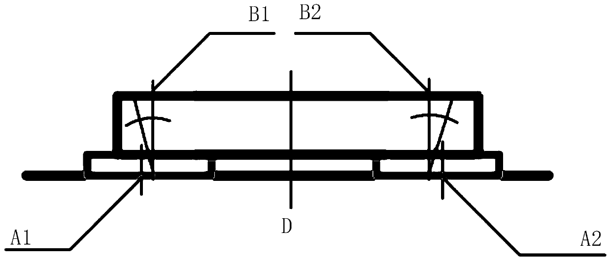
[0036] refer to figure 1 , figure 1 It is a structural diagram of components and PCBA boards according to the embodiment of the present invention. The present invention discloses a target point calculation method for flying probe testing, including:

[0037] S1: Load the light drawing file and obtain the design coordinates of the center point of the pad of the PCBA board;

[0038] S2: According to the design coordinates of the center point of the PCBA board pad, the type of tie point, and the type of device package, the target test point and its plane coordinates are obtained, and the design coordinates of the center point of the PCBA board pad and the target test point are calculated. The difference of the plane coordinates of the points;

[0039] S3: Calculate the deviation value of the target test po...


PUM


Abstract

The invention discloses a target point calculation method for a flying probe test, comprising the steps of: S1: loading a light painting file, and obtaining design coordinates of a central point of aPCBA board bonding pad; S2: calculating a target test point and plane coordinates thereof according to the design coordinates of the central point of the PCBA board bonding pad, a pricking point typeand a device package type, and calculating a difference value between the plane coordinates of the target test point and the design coordinates of the central point of the PCBA board bonding pad; S3:calculating a deviation value of the target test point on height; S4: performing distance compensation in combination with the deviation distribution condition of the target test point; and S5: obtaining three-dimensional coordinates of the final target test point. By adopting the target point calculation method disclosed by the invention, by means of the technical means of compensating the difference value between the target test point and the central point of the bonding pad and compensating the height deviation to obtain the coordinates of the final target test point, the problem of inaccurate probe pricking point test in the prior art is overcome, and the purpose of improving the accuracy of electrodes of components and parts in the probe pricking point test is achieved.

Description

technical field [0001] The invention relates to the technical field of automatic testing equipment, in particular to a target point calculation method for flying probe testing. Background technique [0002] Flying probe testing machine is an instrument for testing PCBA boards (printed circuit boards) with high density, many layers, high wiring density and small distance between measuring points. The work is connected to the driver through a multiplex transmission system. (signal generator, power supply, etc.) and sensors (digital multimeter, frequency counter, etc.) to test the components on the circuit board. [0003] With the development of semiconductor process technology, the density and complexity of electronic components on PCBA boards are increasing, and the size of mounted components is decreasing, which requires higher and higher requirements for probe stick test methods. [0004] In the prior art, the coordinates provided by the light-painting file are the design ...

Claims


Application Information

Patent Timeline
IPC IPC(8): G01R35/00G01B11/00G01B11/03
CPCG01B11/002G01B11/03G01R35/005
Inventor 邵勇锋黄亮黄龙汪兴友
Owner 深圳橙子自动化有限公司
Why Eureka
Try Eureka