
Method and system for calculating engine exhaust flow

A technology of exhaust gas flow and calculation method, which is applied in the direction of internal combustion engine testing, multi-programming device, resource allocation, etc. performance, achieve dynamic performance, and improve the effect of operation speed

Active Publication Date: 2022-01-11
SHANDONG UNIV
View PDF2 Cites 0 Cited by
  • Summary
  • Abstract
  • Description
  • Claims
  • Application Information

AI Technical Summary

Problems solved by technology

At present, most of the differential pressure flowmeters adopt the method of continuous fixed-point moving average, which has the following disadvantages: (1) The number of moving average points is large, and the processing speed of the processor is slow; (2) It cannot be linked to the engine speed, and the dynamic Not responsive enough
[0005] The inventor found during the research and development process that the method of measuring engine exhaust flow based on differential pressure usually has higher requirements on the acquisition system, which requires a higher acquisition frequency and resolution, which undoubtedly increases the complexity and price of the system

Method used


Image

  • Method and system for calculating engine exhaust flow
  • Method and system for calculating engine exhaust flow
  • Method and system for calculating engine exhaust flow

Examples


Embodiment 1

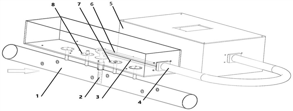
[0038] This embodiment provides an engine exhaust flow calculation system based on the exhaust pressure difference, please refer to the attached figure 1 , the engine exhaust flow calculation system includes a differential pressure acquisition device, a main control device and a rotational speed acquisition device; the differential pressure acquisition device collects current engine exhaust pressure differential data, exhaust temperature data and exhaust absolute pressure data, and transmits To the main control device, the speed acquisition device collects the engine speed data and transmits it to the main control module, and the main control device obtains the current engine exhaust pressure difference data, exhaust temperature data, exhaust absolute pressure data and engine speed data, for The engine exhaust pressure difference data is subjected to nine-point moving average smoothing filter processing, the engine single cycle is calculated according to the speed, the engine s...

Embodiment 2

[0053] This embodiment provides a method for calculating engine exhaust flow based on exhaust pressure difference, which is implemented based on the engine exhaust flow calculation system described in Embodiment 1.

[0054] Please refer to the attached Figure 4 , the engine exhaust flow calculation method based on the exhaust pressure difference comprises the following steps:

[0055] S101. Obtain current engine exhaust pressure differential data, exhaust temperature data, exhaust absolute pressure data, and engine speed data.

[0056] In this embodiment, the current engine exhaust pressure differential data, exhaust temperature data and exhaust absolute pressure data are collected by the differential pressure acquisition device, and transmitted to the main control device.

[0057] In this embodiment, the acquisition of the rotational speed has the following methods:

[0058] (1) Obtain the rotational speed according to the rotational speed sensor equipped with the engine. ...


PUM


Abstract

The invention discloses an engine exhaust flow calculation method and system based on the exhaust pressure difference, which can calculate the engine exhaust flow according to the real-time rotational speed of the engine. The method includes the following steps: obtaining current engine exhaust pressure differential data, engine exhaust temperature data, engine exhaust absolute pressure data and engine speed data; performing multi-point moving average smoothing filter processing on the current engine exhaust pressure differential data; According to the engine speed, calculate the single cycle period of the engine; calculate the average points of the engine exhaust pressure difference according to the single cycle period of the engine; average the current engine exhaust pressure difference data after multi-point moving average smoothing according to the average points of the pressure difference, and obtain Engine average exhaust pressure difference; use the engine average exhaust pressure difference to calculate the engine exhaust flow value.

Description

technical field [0001] The present disclosure relates to the technical field of engine testing, in particular to a method and system for calculating engine exhaust flow based on exhaust pressure difference. Background technique [0002] As an indispensable power output device for human society, the engine plays a vital role in our daily life. From the design and development of the engine to the loading application, there are several tests in between. Especially in today's increasingly stringent emission regulations, engine emission testing is becoming more and more important. The engine exhaust flow rate is a crucial parameter in engine testing. Based on this parameter, the engine emission value can be estimated and compared with regulations. [0003] The exhaust flow of the engine is due to its high temperature, large pulsation, and the fact that the flow detection equipment cannot produce a large pressure drop, which affects the normal operation of the engine. At present...

Claims


Application Information

Patent Timeline
Patent Type & Authority Patents(China)
IPC IPC(8): G01M15/10G01M15/05G06F9/50
CPCG06F30/20
Inventor 程勇于文龙
Owner SHANDONG UNIV
Learn More