Method for solving burst of photovoltaic vacuum glass and photovoltaic vacuum glass

A vacuum glass and photovoltaic technology, applied in the direction of photovoltaic power generation, renewable energy integration, sustainable buildings, etc., can solve problems such as bursting, affecting product application and industry development, and bursting of photovoltaic vacuum glass to achieve convenient replacement, excellent safety and reliability The effect of high performance and excellent thermal insulation performance

Inactive Publication Date: 2019-10-15
许浒
View PDF5 Cites 0 Cited by
  • Summary
  • Abstract
  • Description
  • Claims
  • Application Information

AI Technical Summary

Problems solved by technology

[0007] The purpose of the present invention is to solve the existing photovoltaic vacuum glass. Due to the strong thermal expansion and deformation stress that is difficult to release due to the vacuum glass body and the inner glass support column, resulting in bursting, which seriously affects product application and industry development, and provides The method for solving the bursting of photovoltaic vacuum glass and a kind of photovoltaic vacuum glass produced by said method

Method used


Image

  • Method for solving burst of photovoltaic vacuum glass and photovoltaic vacuum glass
  • Method for solving burst of photovoltaic vacuum glass and photovoltaic vacuum glass
  • Method for solving burst of photovoltaic vacuum glass and photovoltaic vacuum glass

Examples


Embodiment 1

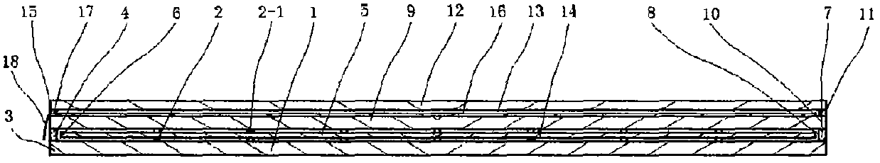
[0028] Embodiment one, according to Figure 1 Shown:

[0029] (1) Arrange pins 2 at corresponding positions on the surface of the inner flat glass 1, and arrange low-temperature sealing material 4 for sealing edges with a melting temperature of 300°C-450°C around the periphery 3 of the inner flat glass.

[0030] (2) Place the heat energy attenuation and dispersion separation layer 5 on the pin 2, and leave a 2mm-10mm thermal expansion gap 8 between the heat energy attenuation and dispersion separation layer periphery 6 and the sealing edge 7 to release the heat energy attenuation and dispersion separation Thermal expansion deformation stress of layer 5 after heating.

[0031] (3) Arrange the second-layer column pins 2-1 at corresponding positions on the surface of the thermal energy attenuation and dispersion separation layer 5, and align the upper and lower column pins.

[0032] (4) Place the outer flat glass 9 on the second-layer pin 2-1, and make the periphery 10 of the o...

Embodiment 2

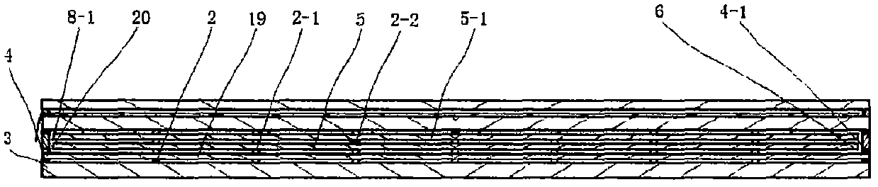
[0037] Embodiment two, according to Figure II Shown:

[0038]According to the method described in Embodiment 1, a vacuum separation layer 19 is first placed on the column pin 2, and the lower surface of the periphery of the vacuum separation layer 20 is fully connected with the sealing edge low-temperature sealing compound 4 arranged on the periphery 3 of the inner flat glass; Arrange the second-layer column pins 2-1 at the corresponding positions of the separation layer 19, and arrange the sealing edge low-temperature sealing material 4-1 with a melting temperature of 300°C-450°C on the upper surface of the periphery 20 of the vacuum separation layer; Place the thermal energy attenuation and dispersion separation layer 5 on the column pin 2-1, and leave a 2mm-10mm thermal expansion gap 8-1 between the periphery of the thermal energy attenuation and dispersion separation layer 6 and the sealing edge low-temperature sealing material 4-1; Three layers of pillar pins 2-2 are ar...

Embodiment 3

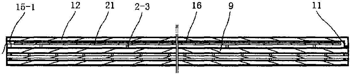
[0039] Embodiment three, according to Figure three Shown:

[0040] After the material assembly is completed according to the method described in Embodiment 1 and 2, a protective glass low-temperature sealing material 11 with a melting temperature of 300°C-450°C is placed on the two or three sides opposite to the outer flat glass 9, and a placement port will be provided. The protective glass 12 of 15-1 and the pin 2-3 of the heat dissipation placement plate 21 are placed on the protective glass low-temperature sealing material 11; then it is made as described in (7) of Embodiment 1; Place the opening 15-1, place the solar cell or battery film 16 on the heat dissipation placement plate 21, seal the placement opening 15-1 with the sealing material 17, and lead the wire 18 out of the sealing material 17, that is, complete the heat dissipation placement The fabrication of a photovoltaic vacuum glass of the plate.


PUM


Abstract

The invention has the obvious advantages that a heat dissipation placement plate and a heat energy attenuation disperse separation layer can greatly reduce partial heat conducted to inner plate glassby support columns, and make the heat conducted by partial several support columns dispersed to multiple support columns in a large area in a disperse manner, and then, conducted to the inner plate glass, thereby balancing and significantly reducing the strong local thermal expansion stress of the inner plate glass and solving the problem that an existing photovoltaic vacuum glass substrate is easy to burst, and product application and industry development are seriously affected; through a solar cell placement port, a photovoltaic cell can be easily replaced and maintained conveniently; through combined action of a multi-vacuum layer and a high-thickness vacuum layer, excellent insulation performance and excellent safety and reliability of the product are ensured; durability is several times greater than that of existing products, and besides, through easy maintenance, the product truly achieves the same life as a building; the product has a broad market prospect; and power generation,heat preservation, lighting and decoration functions are integrated, thereby fully meeting comprehensive requirements for saving energy by 75% and for doors and windows, curtains, walls and roofs bypassive and zero-energy buildings.

Description

technical field [0001] The invention belongs to the technical field of photovoltaic power generation and energy-saving building materials production, and specifically relates to solving the problem of photovoltaic vacuum glass [0002] A bursting method and a photovoltaic vacuum glass made by the method. Background technique [0003] The existing photovoltaic vacuum glass is a vacuum glass surface composed of two parallel flat glasses, and the compound solar power [0004] pool and protective glass. Existence: 1. Vacuum glass is prone to bursting. Reasons: (1) The support column between the two pieces of glass is a stainless steel sheet with a thickness of only 0.12mm. Because the thermal conductivity of the stainless steel sheet is as high as 17W / m.K, which is 17-20 times the thermal conductivity of the glass, the surface glass is subjected to The heat energy is directly transmitted to the inner glass with almost no attenuation through the stainless steel support column ...

Claims


Application Information

Patent Timeline
Patent Type & Authority Applications(China)
IPC IPC(8): H01L31/048H01L31/052H01L23/00
CPCH01L23/562H01L31/0488H01L31/052Y02B10/10Y02E10/50
Inventor 许浒许敬修
Owner 许浒
Why Eureka
Try Eureka