Power cable peeling device

A power cable and cable technology, which is applied to cable installation devices, cable installation, and equipment for dismantling/armored cables, etc., can solve the problems of difficult peeling and low work efficiency, and achieve high cutting efficiency, easy control, Easily adjustable effects

Inactive Publication Date: 2019-10-15
陈小莹 +2
View PDF7 Cites 5 Cited by
  • Summary
  • Abstract
  • Description
  • Claims
  • Application Information

AI Technical Summary

Problems solved by technology

[0003] In the prior art, the wire knife of the common simple wire stripping mechanism is generally cylindrically slidably set on the bracket. In many cases, the peeling of the cable is difficult due to aging and other conditions, and the stripping is inexhaustible, and it is not easy to fall off after cutting. It has resulted in the need for a large amount of manual review and cleaning after mechanical peeling, and the work efficiency is very low

Method used


Image

  • Power cable peeling device
  • Power cable peeling device
  • Power cable peeling device

Examples


Embodiment 1

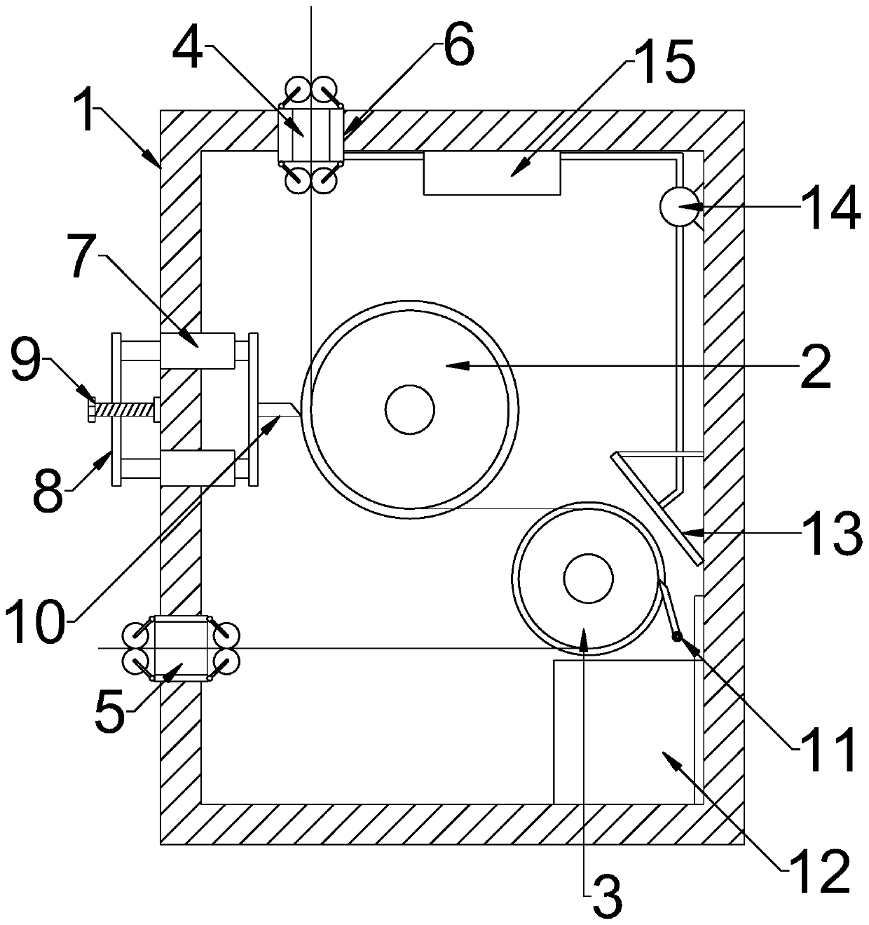
[0023] see Figure 1~3 , in an embodiment of the present invention, a power cable stripping device includes a housing 1, and the inner radial rotation of the housing 1 is provided with a first rotating wheel 2 for supporting the cutting of the cable sheath and for supporting the cable stripping The second rotating wheel 3, the side of the housing 1 is also connected with a cutting structure corresponding to the first rotating wheel 2, and the side of the second rotating wheel 3 in the housing 1 is also connected with a strap 11, The ends of the straps 11 are movably attached to the surface of the second rotating wheel 3 .

[0024] Both the first rotating wheel 2 and the second rotating wheel 3 have a ring-shaped concave surface, and the second rotating wheel 3 is located on the lower side of the first rotating wheel 2; The side wall of the casing 1 above the wheel 2 is provided with an inlet hole 4, and the side wall of the casing 1 corresponding to the left side of the secon...

Embodiment 2

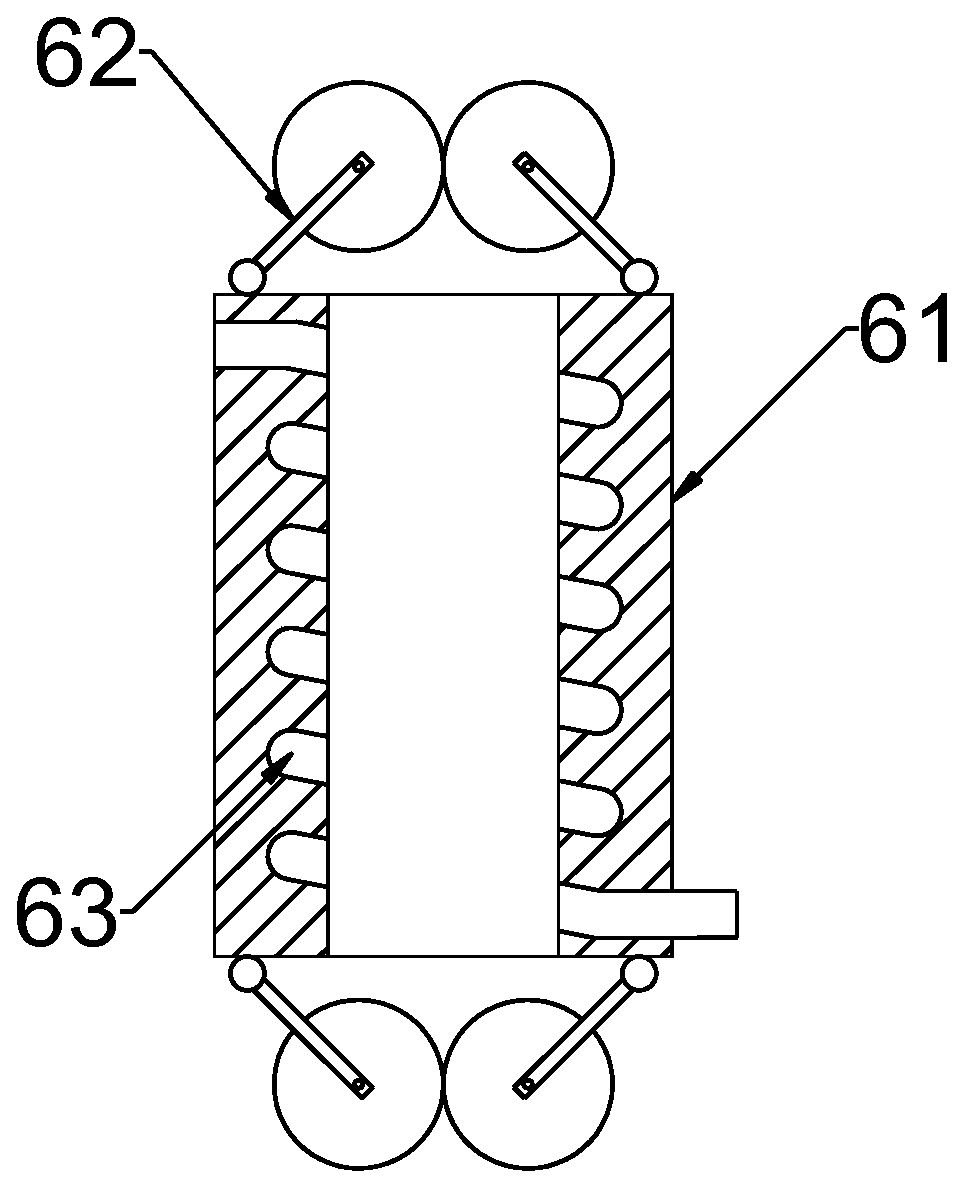
[0029] see figure 1 and 4 , in the embodiment of the present invention, a power cable stripping device, on the basis of embodiment 1, the end of the bush 61 is also connected with an air heating structure, and the air heating structure inlet end is connected with a The air inlet plate 13, the air inlet plate 13 is a hollow plate with through holes evenly distributed on the surface, the opening side of the air inlet plate 13 is opposite to the second rotating wheel 3, and is fixed on the inner wall of the housing 1 by a bracket In this way, the airflow enters and heats through the air inlet plate 13, and then discharges through the bushing 61. When the cable enters, the surface is heated, and the cutting efficiency is higher. After the outer skin is cut, in order to improve the efficiency of peeling, the air inlet plate 13 is The wind generates air flow, and the cold air enters through the air inlet plate 13. When passing through, the cable passing around the second rotating w...


PUM


Abstract

The invention discloses a power cable peeling device, comprising a housing, wherein the housing is provided with an wire inlet and an wire outlet; a first rotating wheel for supporting the cutting ofa cable sheath and a second rotating wheel for supporting the peeling of the cable are rotatably disposed in the housing in the radial direction; the side of the housing is further connected with a cutting structure corresponding to the first rotating wheel; the side of the second rotating wheel is also connected with a lap piece in the housing; the tail end of the lap piece is movably attached tothe surface of the second rotating wheel; wire guiding structures are connected in the wire inlet and the wire outlet; the tail end of a bushing is further connected with an air heating structure; and the air intake of the air heating structure is in communication with an air intake plate. The power cable peeling device can be adjusted and automatically peel the cable after cutting, and improvesthe peeling efficiency in cooperation with the air heating structure.

Description

technical field [0001] The invention relates to the technical field of electric wire processing, in particular to a power cable stripping device. Background technique [0002] A wire is a wire that transmits electrical energy. Divided into bare wire, magnet wire and insulated wire. Bare wires have no insulation layer, including copper, aluminum flat wires, overhead stranded wires, and various profiles (such as profiled wires, bus bars, copper bars, aluminum bars, etc.). It is mainly used for outdoor overhead and indoor busbars and switch boxes. [0003] In the prior art, the wire knife of the common simple wire stripping mechanism is generally cylindrically slidably set on the bracket. In many cases, the peeling of the cable is difficult due to aging and other conditions, and the stripping is inexhaustible, and it is not easy to fall off after cutting. Just caused need a large amount of artificial review cleaning after mechanical peeling, and work efficiency is very low. ...

Claims


Application Information

Patent Timeline
Patent Type & Authority Applications(China)
IPC IPC(8): H02G1/12
CPCH02G1/1251
Inventor 万元强
Owner 陈小莹
Why Eureka
Try Eureka