Motor stator-rotor co-assembly device and method

A stator-rotor and stator technology is applied in the field of motor stator-rotor assembling devices, which can solve the problems of long matching length between the motor end cover and the stator mouth, low position accuracy of the manually hoisted rotor, damage to stator windings and bearings, etc. Manual work intensity, high versatility and practicability, and the effect of interference fit

Pending Publication Date: 2019-10-15
CSR ZHUZHOU ELECTRIC CO LTD
View PDF0 Cites 4 Cited by
  • Summary
  • Abstract
  • Description
  • Claims
  • Application Information

AI Technical Summary

Problems solved by technology

[0007] ① The position accuracy of the manual hoisting rotor is low, and it is easy to cause damage to the stator windings and bearings during the assembly process
[0008] ② The waiting time of the crane is long, and the lifting operation efficiency is low
[0009] ③ Part of the motor end cover and the stator notch have a large matching length, and when the notch size of the spare parts is within the limit deviation, the combined operation of the stator and the rotor needs to be tightened at both ends of the motor at the same time, requiring two people to work together, and the work efficiency is low

Method used


Image

  • Motor stator-rotor co-assembly device and method

Examples


Embodiment Construction

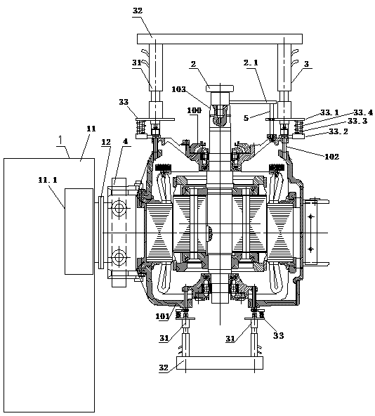
[0028] Combine below figure 1 Embodiments of the present invention are described in detail.

[0029] The motor stator and rotor assembly device is characterized in that it includes a stator displacement device 1 for driving the stator to rotate to change the axial orientation of the stator, a grabbing hanger 2 for hoisting the rotor, and a rotor end cover 100 and stator frame for automatically tightening The bolt automatic tightening device 3 of the connecting bolt 102 between 101, the stator displacement device 1 is connected with the stator base 101, the grabbing hanger 2 is connected with the rotor shaft extension end 103, the bolt automatic tightening device 3 is connected with the connecting bolt 102, The rotor is loaded into the stator as the connecting bolts 102 are tightened, and the rotor end cover 100 is interference fit with the stator frame 101 as the connecting bolts 102 are tightened.

[0030] In the motor stator-rotor assembly device as shown in the figure, the...


PUM


Abstract

The invention discloses a motor stator-rotor co-assembly device and method. The motor stator-rotor co-assembly device comprises a stator displacement device for driving a stator to rotate to change the axial direction of the stator, a grabbing hanger for hanging a rotor and a bolt automatic tightening device for automatically tightening a connecting bolt between a rotor end cover and a stator stock, wherein the stator displacement device is connected with the stator stock; the grabbing hanger is connected with a rotor shaft extending end; the bolt automatic tightening device is in matched connection with the connecting bolt; the rotor is assembled to the stator along with tightening of the connecting bolt; and the rotor end cover is in interference fit with the stator stock along with tightening of the connecting bolt. Automatic transposition of the stator and positioning after transposition can be realized, the stator and the rotor are ensured to complete vertical co-assembly along avertical direction, when the connecting bolt is completely tightened, stator-rotor co-assembly is realized, interference fit assembly between the rotor end cover and the stator stock is also realized,and the stator-rotor co-assembly automation level is improved, and the universality and the practicability are high.

Description

technical field [0001] The invention relates to a motor stator and rotor assembly device and method, and belongs to the technical field of motor stator and rotor assembly. Background technique [0002] The combination of stator and rotor of traction motor has always been a technical problem, mainly for the following reasons: [0003] 1. The air gap of the traction motor is small, within 2mm; the assembly clearance of the motor bearing is small, within 0.10mm. The iron core length of the stator and the rotor is long, and the assembly stroke of the stator and the rotor is long; when the stator and the rotor are assembled, it is not only necessary to determine the three linear directions of X\Y\Z between the stator and the rotor, but also to determine the three rotations of X\Y\Z direction. During the assembly process, the friction and collision between the stator and rotor can easily cause damage to the stator windings and bearings. [0004] 2. The end caps of various types...

Claims


Application Information

Patent Timeline
Patent Type & Authority Applications(China)
IPC IPC(8): H02K15/02H02K15/16H02K15/14
CPCH02K15/02H02K15/14H02K15/16
Inventor 杨振中郑宇华袁双玲
Owner CSR ZHUZHOU ELECTRIC CO LTD
Why Eureka
Try Eureka