Three-level video information transmission system for full-laser projection
A video information and transmission system technology, which is applied in the direction of using projection device image reproducer, color TV, image communication, etc., can solve the problem that the video image frame rate cannot be increased, and achieve the effect of improving the frame rate and brightness
Active Publication Date: 2019-10-15
江苏镭创高科光电科技有限公司
7 Cites 0 Cited by
AI-Extracted Technical Summary
Problems solved by technology
[0004] However, the usual way to scan the display screen is from left to right and from top to bottom. Due to the speed limit of th...
Method used
[0094] However, using LVDS (Low Voltage Differential Signali...
Abstract
The invention provides a three-level video information transmission system for full-laser projection. Video signals in the three-level video information transmission system are input and then subjected to pixel point reforming, segmenting and packaging processing through the first-level processing subsystem to be distributed to the multiple sets of second-level processing subsystems. The secondaryprocessing subsystem decodes, divides, packages and distributes to the multiple groups of tertiary processing subsystems, the multiple groups of LDs are driven at the same time after being processedby the tertiary processing subsystems, pixel scanning is realized through galvanometer driving, display of a frame of image is completed, and the frame rate and brightness are greatly improved.
Application Domain
Color signal processing circuitsPicture reproducers using projection devices
Technology Topic
GalvanometerThree level +6
Image
Examples
- Experimental program(1)
Example Embodiment
[0048] The technical solutions in the embodiments of the present invention will be clearly and completely described below in conjunction with the accompanying drawings in the embodiments of the present invention. Obviously, the described embodiments are only a part of the embodiments of the present invention, rather than all the embodiments. Based on the embodiments of the present invention, all other embodiments obtained by those of ordinary skill in the art without creative work shall fall within the protection scope of the present invention.
[0049] In order to make the above objectives, features and advantages of the present invention more obvious and understandable, the present invention will be further described in detail below with reference to the accompanying drawings and specific embodiments.
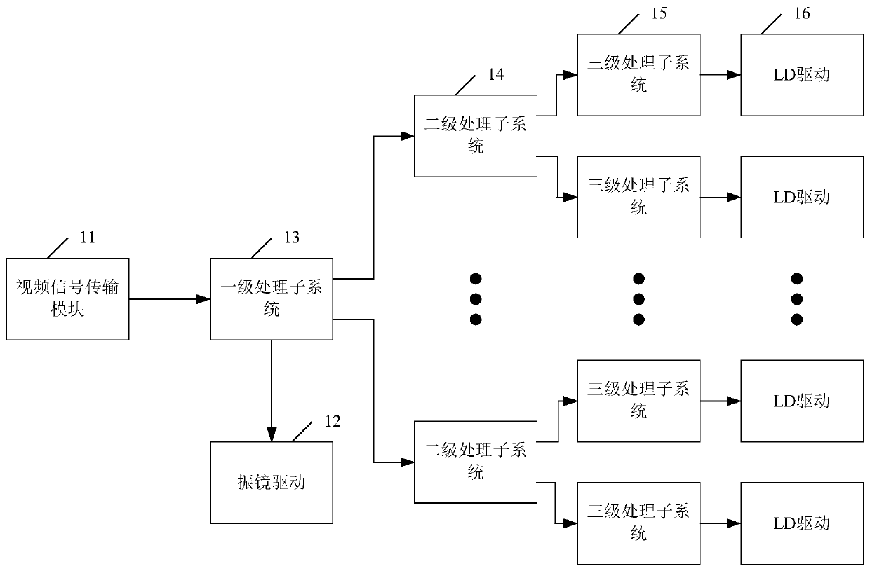
[0050] reference figure 1 , figure 1 This is a schematic structural diagram of a three-level video information transmission system for all laser projection provided by an embodiment of the present invention. The three-level video information transmission system includes: a video signal transmission module 11, a galvanometer drive 12, and a first-level processing subsystem 13 , Multiple secondary processing subsystems 14 communicatively connected with the primary processing subsystem 13, multiple tertiary processing subsystems 15 communicatively connected with each secondary processing subsystem 14 and each LD driver 16 for communication connection with tertiary processing subsystem 15;
[0051] Wherein, the video signal transmission module 11 is used to transmit the video signal to the primary processing subsystem 13 in a pixel serial transmission manner;
[0052] The primary processing subsystem 13 is used to convert the video signal into RGB data, is also used to reverse the even-line RGB data of each frame of image, and is also used to convert the serial transmission mode to parallel The transmission mode is also used to pack the RGB data of each frame of image line by line for even distribution to the secondary processing subsystem 14;
[0053] The secondary processing subsystem 14 is configured to decode the received RGB data and pack it line by line to evenly distribute it to the tertiary processing subsystem 15;
[0054] The three-level processing subsystem 15 is used to decode the received RGB data and divide it into parallel odd or parallel even row data, and simultaneously light up all odd or even LD drivers 16 in a parallel manner to form pixels;
[0055] The galvanometer drive 12 is used to scan the pixels to form an image.
[0056] Specifically, the galvanometer drive 12 includes: a horizontal galvanometer and a vertical galvanometer;
[0057] Wherein, the horizontal galvanometer is used to scan all odd rows of RGB data; that is, the horizontal galvanometer scans all odd rows (or even rows) pixels left and right at the same time by scanning left and right to complete odd frames (or even frames) Display.
[0058] The vertical galvanometer is used for pixel shifting, so that the horizontal galvanometer scans all even rows of RGB data. That is, the vertical galvanometer can realize the offset of the upper and lower two pixels by scanning up and down, so as to realize the switching of odd frames (all odd lines in an image) and even frames, and complete one frame of image display.
[0059] It should be noted that the present invention is only illustrated in the manner of galvanometer scanning, and other fast reflection mirror methods can also be used, such as fast reflection mirror realized by MEMS (Micro Electro Mechanical System) process, fast reflection realized by voice coil motor method Mirror etc.
[0060] In this example, reference figure 2 , figure 2 This is a schematic diagram of input video signal scanning provided by an embodiment of the present invention. The input video signal is transmitted pixel by pixel, that is, the first point of the first line is transmitted first, followed by the second point, until one line The transmission is complete. Then transmit the first point of the next line. In this way, until the last point of the last line, the transmission mode is a pixel serial transmission mode.
[0061] reference image 3 , image 3 This is a schematic diagram of all-laser projection video signal scanning provided by an embodiment of the present invention. When the galvanometer scanning mode of the all-laser projection system is used for imaging, parallel imaging of multiple pixels is adopted, that is, one column of images is displayed at a time. After the mirror scans from one side to the other, all odd lines of the frame are displayed, and then the vertical galvanometer will offset the pixels vertically. When the horizontal galvanometer returns from the side in the opposite direction, all the frames of the frame are completed. Even scanning.
[0062] In this embodiment, this application provides a three-level video information transmission system for all-laser projection. After the video signal is input, the pixels are rearranged and divided by the first-level processing subsystem, and then packaged line by line and distributed to multiple groups of two. Two-level processing subsystem, the two-level processing subsystem decodes and then divides and distributes to multiple groups of three-level processing subsystems, a group of three-level processing subsystems decode the video signal while driving multiple groups of LDs to produce RGB three colors and converge into a single pixel , Through the horizontal galvanometer, the odd lines of a frame of image can be scanned at the same time, and then through the vertical galvanometer to realize the pixel shift, the display of one frame of image can be completed.
[0063] It should be noted that in this application, the operations of odd and even rows can be replaced with each other. For example, the horizontal galvanometer can scan the odd or even rows of a frame of image at the same time, and then the vertical galvanometer can realize the pixel shift. Complete the display of one frame of image.
[0064] For another example, when the horizontal galvanometer scans the even lines of a frame of image at the same time, the odd line data can be reversed.
[0065] In this application, the description is only given in the form of examples and is not limited.
[0066] Further, refer to Figure 4 , Figure 4 It is a schematic structural diagram of a primary processing subsystem provided by an embodiment of the present invention. The primary processing subsystem 13 includes: a color decoding module 41;
[0067] Wherein, the color decoding module 41 is used to convert the video signal into RGB data.
[0068] The primary processing subsystem 13 also includes: a data reverse order module 42;
[0069] Wherein, the data reverse order module 42 is used to reverse order the even row RGB data of each frame of image.
[0070] In this embodiment, since the horizontal galvanometer is deflected in the forward direction, the odd-line parallel pixels are scanned from left to right, so the odd-line video data is defined as a positive sequence. When the horizontal galvanometer is reversely deflected, the parallel pixels of the even rows are scanned from right to left. Relatively speaking, the video data of the even rows are in the reverse order, so the RGB data of the even rows need to be reversed.
[0071] It should be noted that when the horizontal galvanometer is deflected in the forward direction, the even row of pixels can also be scanned from left to right to define the even-line video data as a positive sequence. When the horizontal galvanometer is deflected in the reverse direction, the odd-line parallel pixels are from right to left. Scanning, relatively speaking, the odd-line video data is reversed, and the odd-line RGB data needs to be reversed.
[0072] That is to say, the design of the positive and negative order of the odd and even row data is not only realized by the positive odd rows and the reverse even rows, but also the reverse odd rows and the positive even rows.
[0073] reference Figure 5 , Figure 5 This is a schematic diagram of RAM reading and writing provided by an embodiment of the present invention, refer to Image 6 , Image 6 It is a schematic diagram of a RAM parity row reading provided by an embodiment of the present invention. The data reverse order module 42 includes: a first storage unit RAM0 and a second storage unit RAM1;
[0074] Wherein, the first storage unit RAM0 is used to write odd rows of RGB data point by point, and read the odd rows of RGB data forward;
[0075] The second storage unit RAM1 is used to write the even-row RGB data point by point, and read the even-row RGB data in reverse.
[0076] In this embodiment, as figure 2 As shown, the first row of data is written into the RAM0 area point by point. When the first row of data is completely stored in RAM0, the second row of data is written into the RAM1 area, and the data in RAM0 is read forward. When the second row of data is completely stored in RAM1, the reading of the first row of data is completed. At this time, the third row of data is written to RAM0 point by point, and the data in RAM1 is read in the reverse direction. Reverse order reorganization.
[0077] It should be noted that the embodiment of the present invention only implements the positive and negative sequence reforming in the manner of RAM, and other implementable manners are all within the protection scope of the present invention.
[0078] Further, such as Figure 4 As shown, the primary processing subsystem 13 further includes: a DDR storage module 43;
[0079] Wherein, the DDR storage module 43 is configured to reform the odd-row RGB data read in the forward direction and the even-row RGB data read in the reverse direction into a data structure in which the odd and even rows are parallel.
[0080] In this embodiment, in order to realize the conversion of the video data structure of serial transmission into the data structure of parity and even rows, the video data after the positive and negative sequence is realized by the data reverse sequence module 42 is subjected to data reformation by the DDR storage module 43.
[0081] reference Figure 7 , Figure 7 This is a storage schematic diagram of the DDR memory module provided by the embodiment of the present invention. The odd rows of the first frame of video data are stored in the DDR3_A0 area in the DDR3_A area point by point in a serial manner, and the even rows are stored in the DDR3_A1 area in the DDR3_A area in the same manner. When the first frame of video data is completely stored in the DDR3_A area, the second frame of video data is stored in the DDR3_B area in the same way.
[0082] reference Figure 8 , Figure 8 This is a schematic diagram of the video data structure provided by the embodiment of the present invention. At this time, the odd row data in the DDR3_A0 area is first read in parallel, and then the even row data in the DDR3_A1 area is read in the same manner. When the first frame of video data in the DDR3_A area is read, the second frame of video data is completely stored in the DDR3_B area. At this time, the video data in the DDR3_B area is read in the same way, and the third frame of video data is written into the DDR3_A area. In this way, the ping-pong operation is performed on two adjacent frames of video data, and through the design of read and write address logic, the video data is reformed.
[0083] It should be noted that the present invention is only used as an example to realize the video data reforming method through the DDR memory module, and it can also be realized by FIFO (first in first out), RAM, SDRAM (synchronous dynamic random access memory) and IC chip.
[0084] Further, such as Figure 4 As shown, the primary processing subsystem 13 further includes: a reading module 44;
[0085] Wherein, the reading module 44 is configured to pack the RGB data of each frame of image line by line for even distribution to the secondary processing subsystem 14.
[0086] In this example, reference Picture 9 , Picture 9 This is a schematic diagram of video data line segmentation provided by an embodiment of the present invention. The reshaped data is then divided into lines by the reading module, and then packaged and converted into LVDS (low voltage differential signal) for distribution to multiple groups of secondary processing subsystems. .
[0087] Further, refer to Picture 10 , Picture 10 It is a schematic structural diagram of a secondary processing subsystem provided by an embodiment of the present invention. The secondary processing subsystem 14 includes: a first decoding module 101, a first data segmentation module 102, and a packing module 103;
[0088] Wherein, the first decoding module 101 is configured to decode the received RGB data;
[0089] The second data segmentation module 102 is used to segment the decompressed RGB data;
[0090] The packaging module 103 is used to perform line-by-line packaging processing for even distribution to the three-level processing subsystem.
[0091] In this embodiment, since the primary processing subsystem cannot suspend the multi-level tertiary processing subsystem, multiple groups of secondary processing subsystems are added to divide the video data again.
[0092] First, the secondary processing subsystem receives the RGB data, first performs the decoding operation, and then writes it to the second data segmentation module for re-segmentation. The segmentation method is the same for the same level processing subsystem, and the segmented RGB data is packaged and converted LVDS (low voltage differential signal) is distributed to multiple groups of three-level processing subsystems.
[0093] It should be noted that the present invention only uses LVDS to transmit video data by way of example, and it can also use TTL (logic gate), RSDS (low swing differential signal), TMDS (minimized transmission differential signal) and other methods for data transmission. transmission.
[0094] However, the use of LVDS (low-voltage differential signaling) transmission mode can improve transmission efficiency.
[0095] Further, refer to Picture 11 , Picture 11 It is a schematic structural diagram of a three-level processing subsystem provided by an embodiment of the present invention. The three-level processing subsystem 15 includes: a second decoding module 111, a second data segmentation module 112, and an LD driving module 113;
[0096] Wherein, the second decoding module 111 is configured to decode the received RGB data;
[0097] The second data dividing module 112 is configured to divide the decompressed RGB data into parallel odd rows or parallel even rows;
[0098] The LD driving module 113 is used for LD driving to simultaneously light up all odd or even rows in parallel to form pixels.
[0099] In this embodiment, the three-level processing subsystem is mainly responsible for decoding, reforming and LD driving the received RGB data.
[0100] First, the data sent by the secondary processing subsystem is decoded, and the second data splitting module performs cross-clock domain processing, and splits it into parallel odd or even video data, and drives multiple groups of LDs in parallel to achieve simultaneous Light up all odd or even LD.
[0101] The above provides a detailed introduction to the three-level video information transmission system for all laser projection provided by the present invention. Specific examples are used in this article to explain the principle and implementation of the present invention. The description of the above embodiments is only for help Understand the method of the present invention and its core idea; at the same time, for those of ordinary skill in the art, according to the idea of the present invention, there will be changes in the specific implementation and the scope of application. In summary, the content of this specification does not It should be understood as a limitation of the present invention.
[0102] It should be noted that the various embodiments in this specification are described in a progressive manner, and each embodiment focuses on the differences from other embodiments. For the same and similar parts between the various embodiments, refer to each other. can. For the device disclosed in the embodiment, since it corresponds to the method disclosed in the embodiment, the description is relatively simple, and the relevant information can be referred to the description of the method part.
[0103] It should also be noted that in this article, relational terms such as first and second are only used to distinguish one entity or operation from another entity or operation, and do not necessarily require or imply these entities or operations. There is any such actual relationship or order between. Moreover, the terms "include", "include", or any other variants thereof are intended to cover non-exclusive inclusion, so that a process, method, article, or device inherent to a series of elements is included, or is also included in these processes , Methods, articles or equipment inherent elements. If there are no more restrictions, the element defined by the sentence "including a..." does not exclude the existence of other same elements in the process, method, article, or equipment including the element.
[0104] The foregoing description of the disclosed embodiments enables those skilled in the art to implement or use the present invention. Various modifications to these embodiments will be obvious to those skilled in the art, and the general principles defined in this document can be implemented in other embodiments without departing from the spirit or scope of the present invention. Therefore, the present invention will not be limited to the embodiments shown in this document, but should conform to the widest scope consistent with the principles and novel features disclosed in this document.
PUM


Description & Claims & Application Information
We can also present the details of the Description, Claims and Application information to help users get a comprehensive understanding of the technical details of the patent, such as background art, summary of invention, brief description of drawings, description of embodiments, and other original content. On the other hand, users can also determine the specific scope of protection of the technology through the list of claims; as well as understand the changes in the life cycle of the technology with the presentation of the patent timeline. Login to view more.